Glass-like carbon deformed molded article, process for producing the same, and joint structure for jointing a connecting member to a glass-like carbon hollow molded article

Inactive Publication Date: 2005-10-20
KOBE STEEL LTD
View PDF15 Cites 16 Cited by
  • Summary
  • Abstract
  • Description
  • Claims
  • Application Information

AI Technical Summary

Benefits of technology

[0021] In light of the above-mentioned situation, the present invention has been made. An object thereof is to provide a process for producing a glass-like carbon deformed molded article, which has a deformed cross section (typically, an elliptical section or a section composed of partial circles and linear portions), such as a glass-like carbon member in a deformed pipe form or a bend pipe, with relative ease and a good dimensional accuracy; and a glass-like carbon defo

Problems solved by technology

However, glass-like carbon has problems about production technique thereof that the thermosetting resin which is raw material thereof has a low moldability and the resin is shrunken by about 20% in the carbonization.
Thus, it is not easy to fabricate glass-like carbon member having a complicated shape with a high precision.
It is however impossible in principle to produce such a deformed molded article by centrifugal molding.
However, this document does not disclose the production of a deformed pipe, such as a pipe which has an elliptical section or has a section composed of partial circle portions and linear portions.
However, the process has drawbacks that a large complicated metal mold is required to be used and the steps of molding the resin are complicated.
It is essentially difficult to form parts of the pipe with a high dimensional accuracy and further position these parts accurately so as to be jointed with each other.
This is because joint lines frequently cause dimensional strain, residual stress, and the generation of dust.
Regarding dimensional accuracy, the same problem applies to the case where cores are used.
A drawback of the method using a core is that dimension-correcting effect of the core is insufficient since the gap between the core and a thermosetting resin molded article, which is a product, is large at the time of starting the carbonization of the article.
In

Method used


Image

  • Glass-like carbon deformed molded article, process for producing the same, and joint structure for jointing a connecting member to a glass-like carbon hollow molded article
  • Glass-like carbon deformed molded article, process for producing the same, and joint structure for jointing a connecting member to a glass-like carbon hollow molded article
  • Glass-like carbon deformed molded article, process for producing the same, and joint structure for jointing a connecting member to a glass-like carbon hollow molded article

Examples


example 1

[0095] A commercially available liquid phenol resin (Resitop PL-4804, manufactured by Gunei Chemical Industry Co., Ltd.) was subjected to heat treatment at 100° C. under a reduced pressure for 1 hour to adjust the water content therein. The resultant was used as a raw material of glass-like carbon. A centrifugal molding die having an inside diameter of 325 mm and a length of 1600 mm was used to mold this raw material by centrifugal molding, thereby yielding a phenol resin cylinder of 320 mm diameter and 3.5 mm thickness. The glass transition point thereof was 65° C.

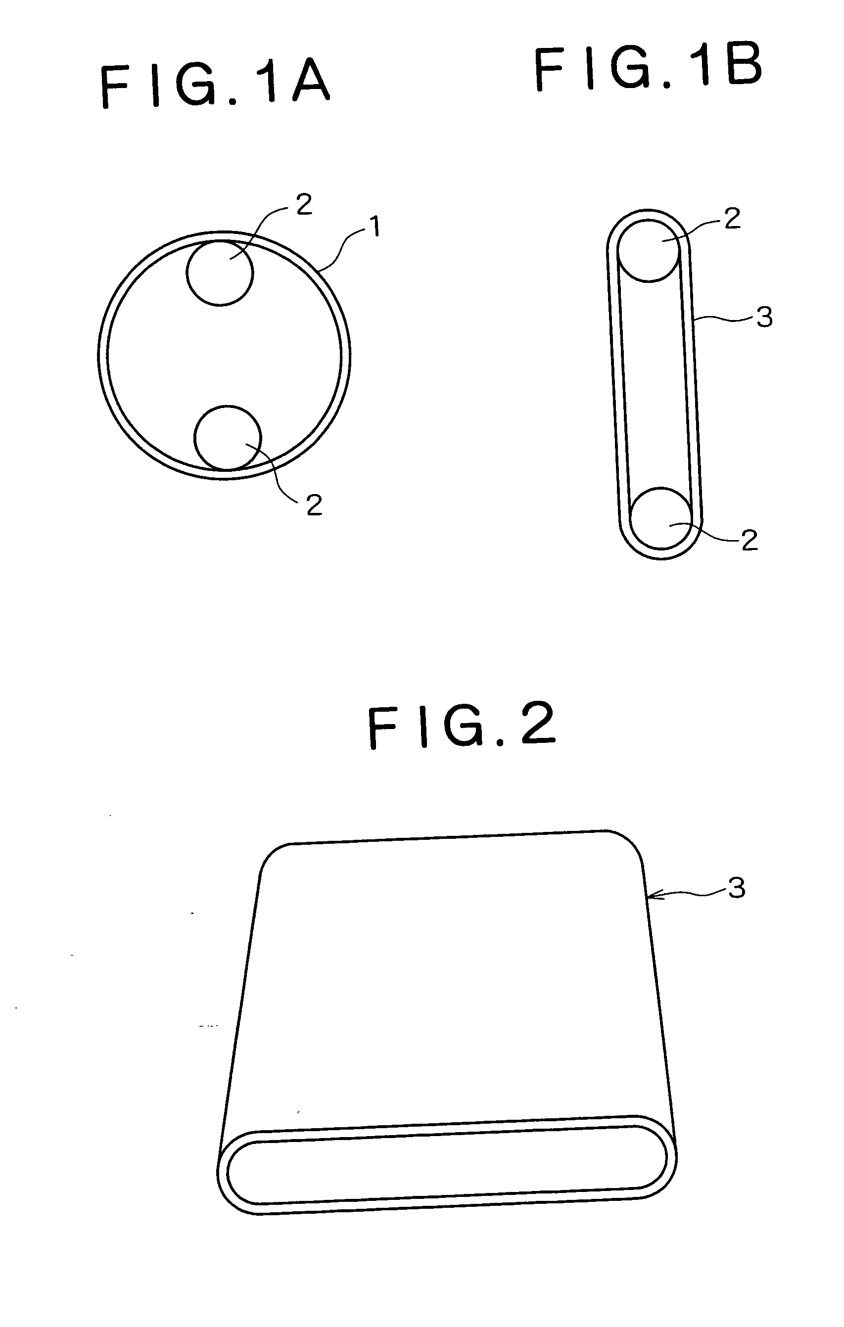
[0096] The resultant cylinder was cut into a length of 600 mm. As illustrated in FIG. 1, two stainless steel pipes (rodlike tools) of 60 mm outside diameter and 600 mm length were inserted into the cut cylinder. One thereof was put so as to hold the cylinder and the other was put as a load on the bottom of the cylinder (see FIG. 1A). In this state, the cylinder was heated at 90° C. for 5 hours to yield a phenol resin def...

example 2

Example wherein a Flange was Jointed to an End of a Pipe

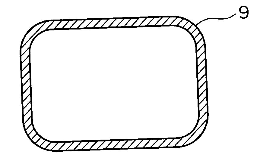
[0097] A phenol resin deformed cylinder having a section in a track form was yielded by the same production process as in Example 1. Separately, the same raw material as used in Example 1 was used and molded into a phenol resin pipe of 3 mm thickness by centrifugal molding. The molded pipe was cut open to yield a phenol resin plate of 3 mm thickness. From this plate, a resin plate in a track and doughnut form was cut out, which had a width of 86 mm, a parallel portion length of 425 mm and a circular portion radius of 33 mm, and had, at the center thereof, a hole having a shape equal to the external shape of the above-mentioned track-form phenol resin deformed cylinder. The two members were jointed to each other with a phenol resin, and the resultant was carbonized in the same usual way as in Example 1, so as to yield a glass-like carbon deformed pipe, 480 mm in total length, having a section composed of circular portions of 48...

example 3

Example wherein a Core was Used

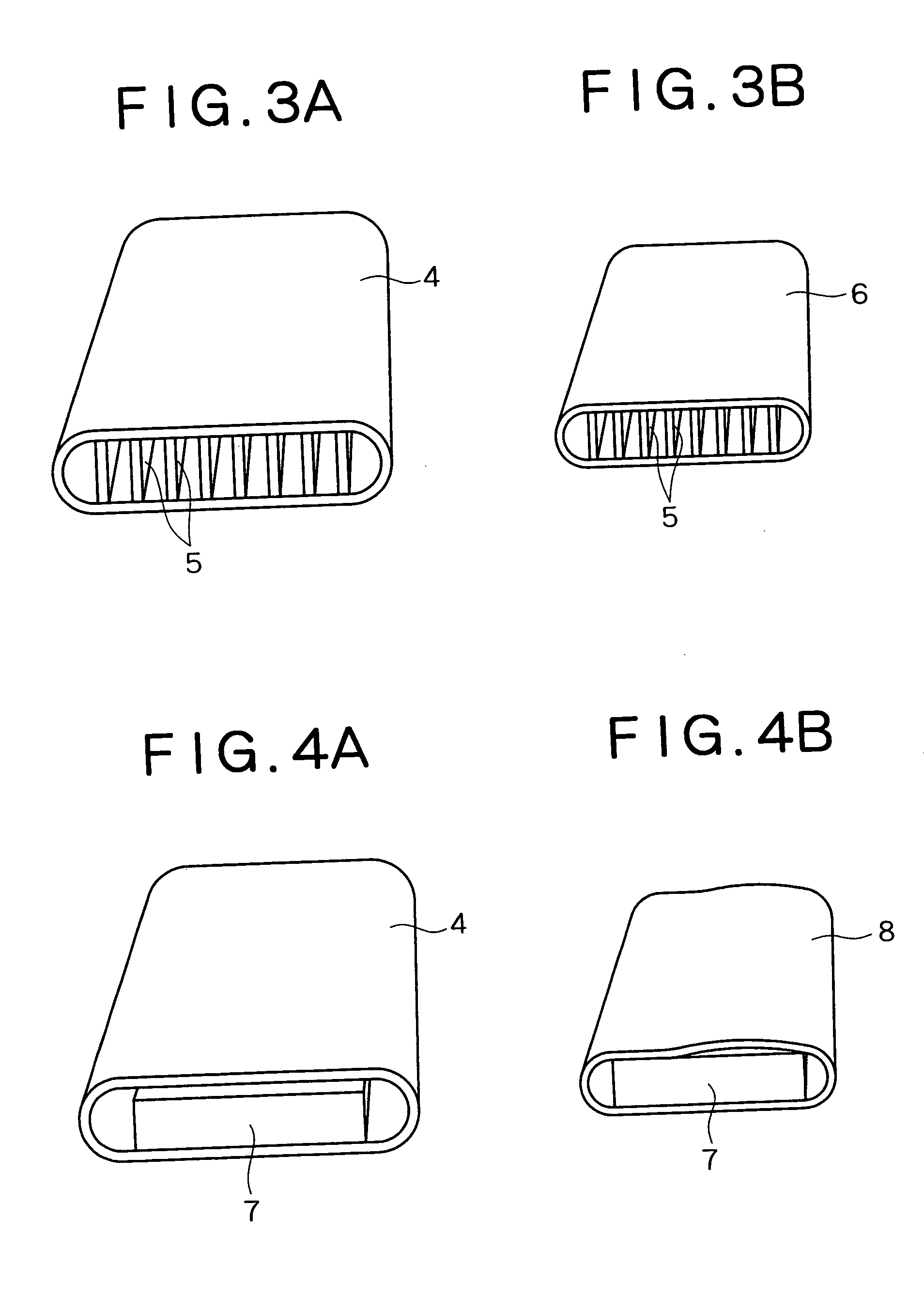
[0098] A commercially available liquid phenol resin (Resitop PL-4804, manufactured by Gunei Chemical Industry Co., Ltd.) was subjected to heat treatment at 100° C. under a reduced pressure for 1 hour to adjust the water content therein. The resultant was used as a raw material of glass-like carbon. A centrifugal molding die having an inside diameter of 325 mm and a length of 1600 mm was used to mold this raw material by centrifugal molding, thereby yielding a phenol resin cylinder of 320 mm diameter and 3.5 mm thickness.

[0099] The resultant cylinder was cut into a length of 500 mm. As illustrated in FIG. 1, two stainless steel pipes (rodlike tools) of 60 mm outside diameter and 600 mm length were inserted into the cut cylinder. One thereof was put so as to hold the cylinder and the other was put as a load on the bottom of the cylinder (see FIG. 1A). In this state, the cylinder was heated at 90° C. for 5 hours to yield a phenol resin deformed cylinder...


PUM

PropertyMeasurementUnit
Glass transition temperatureaaaaaaaaaa
Temperatureaaaaaaaaaa
Forceaaaaaaaaaa

Abstract

Provided is a process for producing a glass-like carbon deformed molded article having a deformed section (typically, an elliptical section or a section composed of partial circles and linear portions), such as a glass-like carbon member in a deformed pipe form or a bent pipe, with relative ease and a good dimensional accuracy. The process comprises the step of molding a thermosetting resin to yield a thermosetting resin molded article, the step of deforming the thermosetting resin molded article plastically in the state that the article is heated, so as to yield a thermosetting resin deformed article, and the step of carbonizing the resultant thermosetting resin deformed article.

Description

BACKGROUND OF THE INVENTION [0001] 1. Technical Field [0002] The present invention relates to a glass-like carbon deformed molded article suitable as a material for parts used in a high-temperature or corrosive environment, a production for producing the same, and a joint structure for jointing a connecting member to a glass-like carbon hollow molded article. [0003] 2. Related Art [0004] Glass-like carbon exhibits a heat resisting temperature of 2000° C. or higher in an inert atmosphere, and also has excellent corrosion resistance against hydrogen fluoride and fluorine. Accordingly, glass-like carbon is expected to be applied to the following: parts of apparatus wherein corrosive gas is handled and impurities are required to be less generated, such as constituting parts of a semiconductor producing apparatus, in particular, those of a CVD machine (for example, a chamber in a Si wafer annealing device or a gas injection nozzle for injecting a reactant gas which is a material for form...

Claims


Application Information

Patent Timeline
IPC IPC(8): B29C53/08B32B1/08C01B31/02C04B35/524F16L9/10F16L49/04F16L49/06
CPCB29C53/083C04B35/524C04B2235/48C04B2235/602Y10T428/131F16L9/10F16L49/04F16L49/06C04B2235/94
Inventor HAMAGUCHI, MAKIFUJIURA, TAKAYASUKISHIMOTO, KEIJI
Owner KOBE STEEL LTD
Why Eureka
Try Eureka