Methods and apparatus for generating,transmitting and/or using beacons

Active Publication Date: 2016-11-03
JUMIPER NETWORKS INC
View PDF16 Cites 83 Cited by
  • Summary
  • Abstract
  • Description
  • Claims
  • Application Information

AI Technical Summary

Benefits of technology

[0029]Many location systems require special site surveys which are known as supervised training to optimize the location accuracy. The system described here, in some embodiments, uses data from users of the system to continuously optimize the performance of the system. Over time the model parameters for a given area can be optimized continuously based on received signal strength from user data to maximize the probability that the path loss model will accurately detect presence in the zone based on beacon signals transmitted from different base stations by adjusting the parameters to maximize a joint probability that a reporting wireless terminal is in a zone covered by the signals transmitted from multiple different base stations.
[0030]While in some embodiments the presence in a zone is determined based on received beacon signals in other embodiments the beacon signals directly communicate information that is relevant to the zone covered by a beam used to transmit the beacon signal. In such embodiments the use of antenna beam

Problems solved by technology

While placing beacon transmitters at different locations, e.g., at stands corresponding to different items, through out a store to advertise different items and/or communicate different locally relevant information is one way to take advantage of the ability of beacons to communicate locally relevant information to individuals as they move from one location to another in store, there are several disadvantages to using a large number of individual battery operated beacon transmitters.
Beacon transmitters located on stands and/or at ground level are a

Method used


Image

  • Methods and apparatus for generating,transmitting and/or using beacons
  • Methods and apparatus for generating,transmitting and/or using beacons
  • Methods and apparatus for generating,transmitting and/or using beacons

Examples


Embodiment Construction

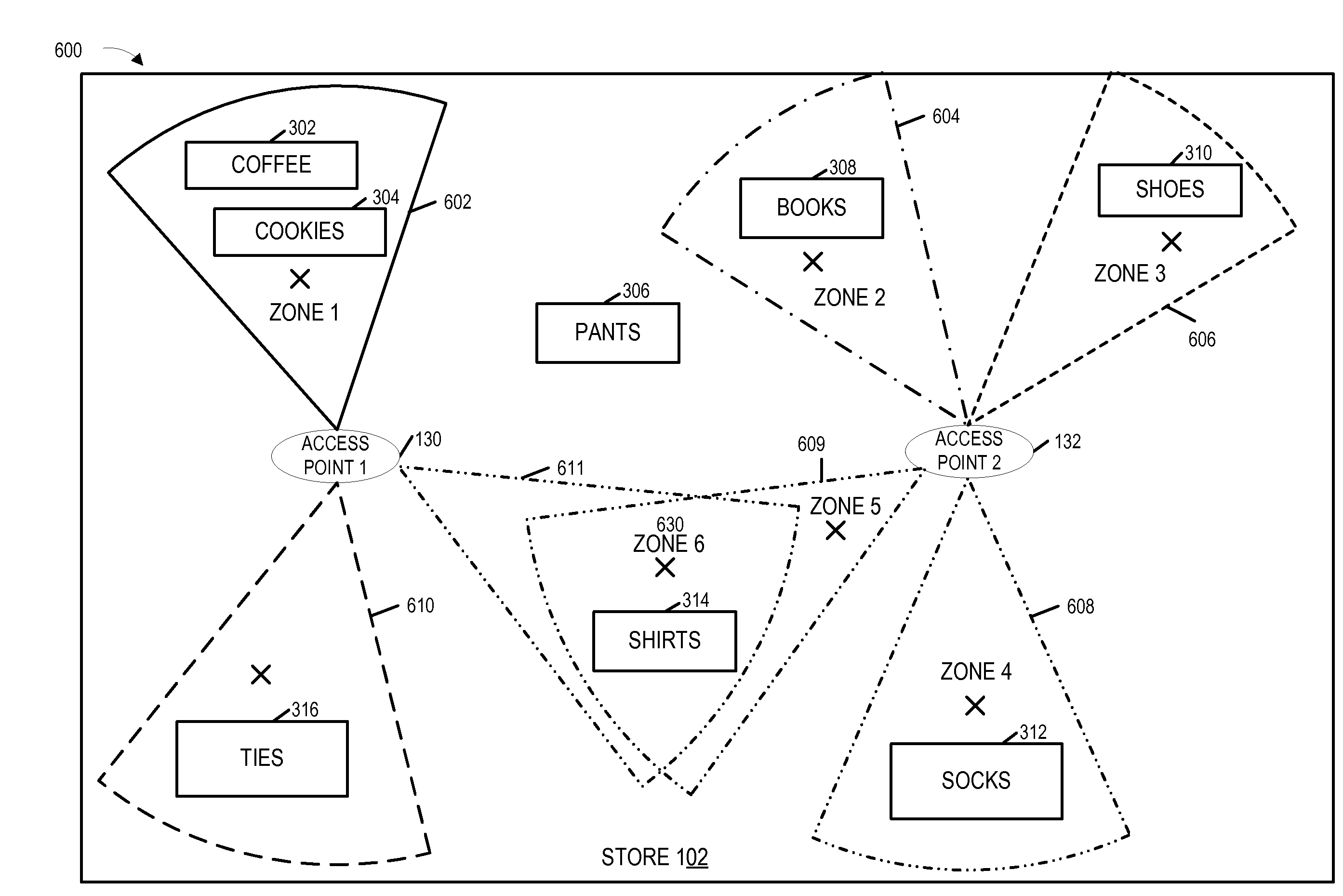
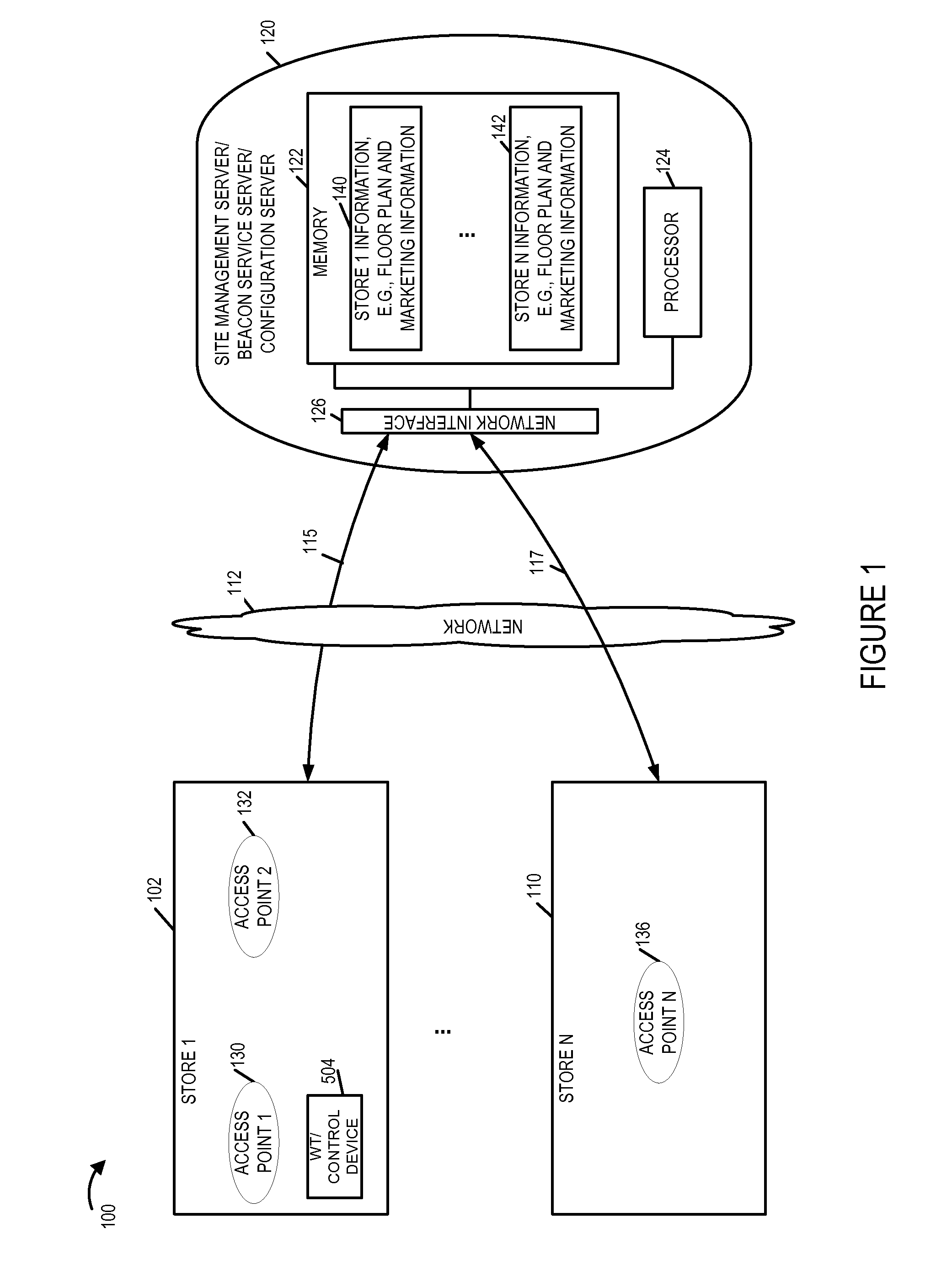
[0069]FIG. 1 is a drawing of an exemplary system 100 implemented in accordance with an exemplary embodiment. Exemplary system 100 supports generation, use and transmission of beacons communicating information to one or more desired regions of interest, e.g., sections of one or more venues.

[0070]Exemplary system 100 includes one or more sites of interest, e.g., stores, a communications network 112, and a site management / beacon / configuration and / or zone correlation server 120. As should be appreciated the configuration, management, zone correlation services can be provided by one server 120 or distributed through a plurality of servers which operate together to provide the functions provided by the exemplary server 120. The server 120 maybe, and sometimes is, located in a network and is thus sometimes referred to as a cloud sever since the physical location of the server is not critical to operation of the system even though the server 120 is normally not located at a customer site. H...


PUM


Abstract

Methods and apparatus for using beacon signals are described. One or more sectorized base stations are used in some embodiments to transmit beacon signals into zones, e.g., each zone being at least partially covered by one or more beacon signals. Use of sectorized base stations allows a single base station, e.g., a Bluetooth or other base station capable of transmitting beacon signals, to cover a number of different zones avoiding the need for multiple different beacon transmitters at different locations to establish different beacon coverage areas. Sectorization of a Bluetooth base station and the ability to remotely or locally configure the base station allows for great flexibility to use beacon signals in stores or other locations without the need for numerous individual battery powered beacon transmitters at floor or display level.

Description

RELATED APPLICATIONS[0001]The present application hereby expressly incorporates U.S. Provisional Patent Application Ser. No. 62 / 197,980 filed Jul. 28, 2015 and U.S. Provisional Patent Application Ser. No. 62 / 155,428 filed Apr. 30, 2015 in their entirety.FIELD[0002]The present application relates to wireless beacons and, more particularly, to methods and / or apparatus for generating, transmitting and / or using beacons.BACKGROUND[0003]Wireless beacons are being used in a wide range of applications. Often wireless beacons are used to transmit identifiers, advertisements, and / or otherwise provide information within range of the wireless beacon transmitter.[0004]One application for beacon transmitters, particularly low power beacon transmitters such as Bluetooth beacon transmitters, is to make users aware of services or special offers in proximity to the beacon transmitter. For example, a coffee shop may use a beacon transmitter to transmit a beacon used to communicate special offers, line...

Claims


Application Information

Patent Timeline
IPC IPC(8): H04W16/28H04W72/04H04W4/02H04W4/00H04W4/021H04W4/80
CPCH04W16/28H04W4/008H04W88/08H04W4/021H04W72/046H04W84/18H04W4/80
Inventor FRIDAY, ROBERTCASTAGNOLI, NEAL DANTEFREI, RANDALL WAYNE
Owner JUMIPER NETWORKS INC
Why Eureka
Try Eureka