Start-up algorithm for an implantable blood pump

Active Publication Date: 2016-11-17
TC1 LLC
View PDF1 Cites 1 Cited by
  • Summary
  • Abstract
  • Description
  • Claims
  • Application Information

AI Technical Summary

Benefits of technology

[0009]The predefined geometric volume denotes a volume for the rotor in which the rotor is operable to pump blood and to rotate freely in a levitated position. When being within the predefined geometric

Problems solved by technology

For such starting algorithms of a rotor in an implantable blood pump, significant cu

Method used


Image

  • Start-up algorithm for an implantable blood pump
  • Start-up algorithm for an implantable blood pump
  • Start-up algorithm for an implantable blood pump

Examples


Example

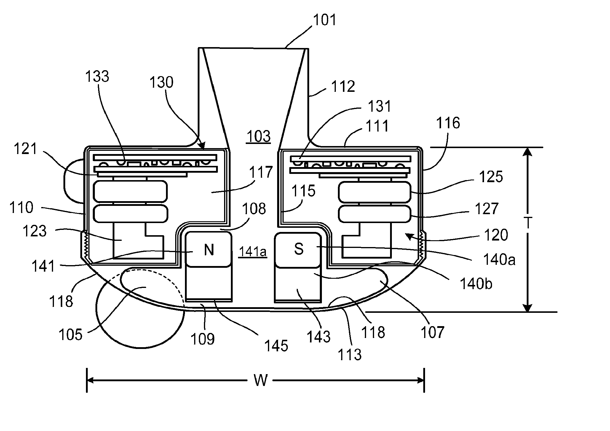
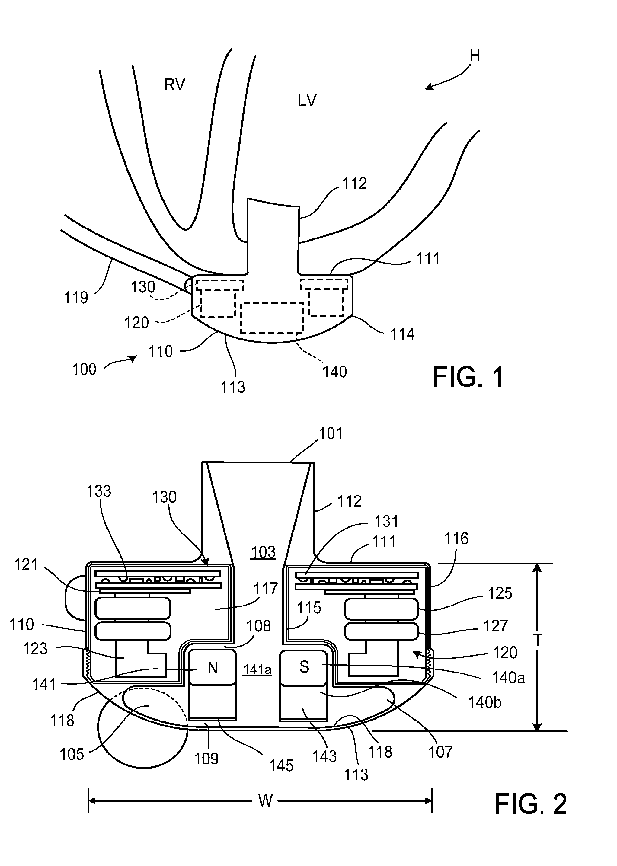
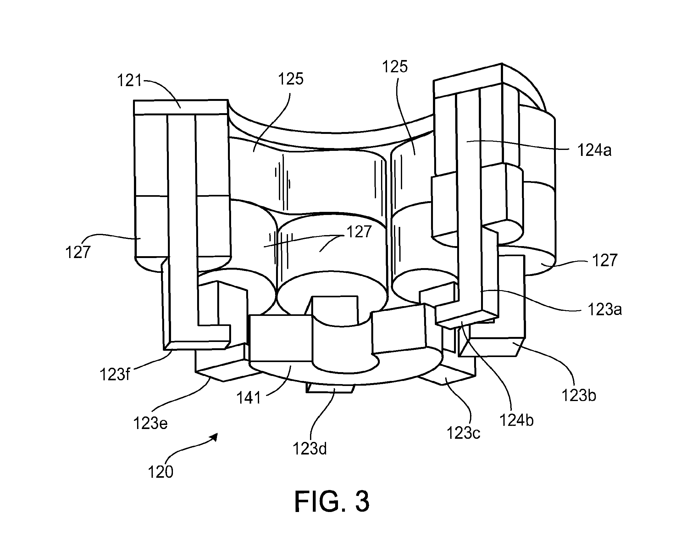
[0072]Reference numbers and designations in the various drawings indicate exemplary aspects, implementations or embodiments of particular features of the present disclosure.

DETAILED DESCRIPTION

[0073]This description relates to a start-up algorithm for an implantable blood pump.

[0074]Specifically, tools and computer-implemented methods for reducing the current demand of implantable blood pumps are described herein.

[0075]The subject matter described in this disclosure can be implemented in particular aspects or embodiments so as to realize one or more of the following advantages.

[0076]First, a current consumption of an implantable blood pump may be reduced. A peak current demanded by a start-up of an implantable blood pump may be reduced. This may prevent a reset of a power supply of an implantable blood pump due to an overload. For example, a peak current of less than 5 ampere may be achieved for the start-up.

[0077]Second, a current needed to perform a rolling of a magnet of a rotor ...


PUM


Abstract

A system and a method for starting a rotor of an implantable blood pump are described. For example, a blood pump system includes a rotary motor having a stator and a rotor. The rotor has permanent magnetic poles for magnetic levitation of the rotor, and the stator has a plurality of pole pieces arranged circumferentially at intervals. The blood pump system includes a controller configured to control a start phase of the rotor, wherein the start phase is prior to the rotor being positioned in a predefined geometric volume for pumping blood and wherein the start phase includes performing a rotation of the rotor by an angle larger than an angle corresponding to a quarter of an angular distance between two neighboring magnetic poles of the rotor.

Description

CROSS-REFERENCES TO RELATED APPLICATIONS[0001]This application is a divisional of U.S. application Ser. No. 14 / 014,957, filed Aug. 30, 2013, which application claims the benefit U.S. Provisional Application No. 61 / 695,469, filed Aug. 31, 2912, the entire contents of which are incorporated herein by reference for all purposes.[0002]The description relates to U.S. Pat. No. 9,091,271, issued Jul. 28, 2015, and titled “Implantable Blood Pump,” the entire contents of which are incorporated herein for all purposes by reference.FIELD[0003]This description relates to motor control, and in various aspects a start-up algorithm, for an implantable blood pump.BACKGROUND[0004]Ventricular assist devices, known as VADs, are implantable blood pumps used for both short-term and long-term applications where a patient's heart is incapable of providing adequate circulation. For example, a patient suffering from heart failure may use a VAD while awaiting a heart transplant. In another example, a patient...

Claims


Application Information

Patent Timeline
IPC IPC(8): A61M1/12F04D1/00F04D29/42F04D13/02F04D15/00A61M1/10F04D7/02
CPCA61M1/127A61M1/1036A61M1/1029A61M1/1015F04D1/00F04D7/02F05B2270/404F04D15/00F04D29/426F05B2270/10F05B2240/30F05B2240/14F04D13/024F04C2270/0421A61M60/422A61M60/148A61M60/232A61M60/814A61M60/585A61M60/88A61M60/178A61M60/538A61M60/822A61M60/419
Inventor SIEBENHAAR, ANDREFLEISCHLI, ANDREAS
Owner TC1 LLC
Why Eureka
Try Eureka