Pneumatic wrench with butterfly steering switching mechanism

a technology of rotating mechanism and pneumatic wrench, which is applied in the field of pneumatic wrench, can solve the problems of inconvenient use, inability of the operator to easily pull the trigger by the index finger, and the drawbacks of conventional pneumatic wrenches, and achieve the effects of improving mechanical parts, low efficiency, and high cos

Inactive Publication Date: 2016-11-17
YEAR CONGRATULATE INDAL
View PDF9 Cites 8 Cited by
  • Summary
  • Abstract
  • Description
  • Claims
  • Application Information

AI Technical Summary

Benefits of technology

[0020]2. The pneumatic wrench with the misalignment of different mechanical structures allows operators to turn on / off the wrench, adjusting the speed, or switching to the forward or reverse rotation with the one-handed operation without changing the holding posture by designing the forward / reverse mechanism above the trigger.
[0021]3. The pneumatic wrench has the manufacturing holes designed on the sidewall of the handle, so that the blank of the casing can be formed by pressure casting to overcome the drawbacks such as the low efficiency and high cost of the traditional gravitational casting method
[0022]4. The pneumatic wrench with improved mechanical parts, the air passage structure is compact, so that the loss of compressed air occurred during the internal transmission of the wrench is reduced to save energy.

Problems solved by technology

According to the using habit of the operator, a right-hand wrench is unable to meet the operation for a left hand operation, since the switch operating lever of the right-hand wrench may be turned by the thumb, but after the user holds the pneumatic wrench by the left hand, the switch operating lever will be situated on a side of the palm, and the thumb will be unable to complete the switching operation, and the switch operating lever is interfered by the index finger.
As a result, the operator cannot pull the trigger by the index finger easily.
In other words, the pneumatic wrench must be designed with left and right structures in order to achieve the one-handed operation, and thus bringing tremendous inconvenience to manufacturers and end-users.
Therefore, the conventional pneumatic wrench has the drawbacks of unable to provide a one-handed operation for all functions or allow left-hand or right-hand operators to share the same wrench.

Method used


Image

  • Pneumatic wrench with butterfly steering switching mechanism
  • Pneumatic wrench with butterfly steering switching mechanism
  • Pneumatic wrench with butterfly steering switching mechanism

Examples


Embodiment Construction

[0048]The aforementioned and other objectives and advantages of the present invention will become clearer in light of the following detailed description of an illustrative embodiment of this invention described in connection with the drawings. It is intended that the embodiments and drawings disclosed herein are to be considered illustrative rather than restrictive.

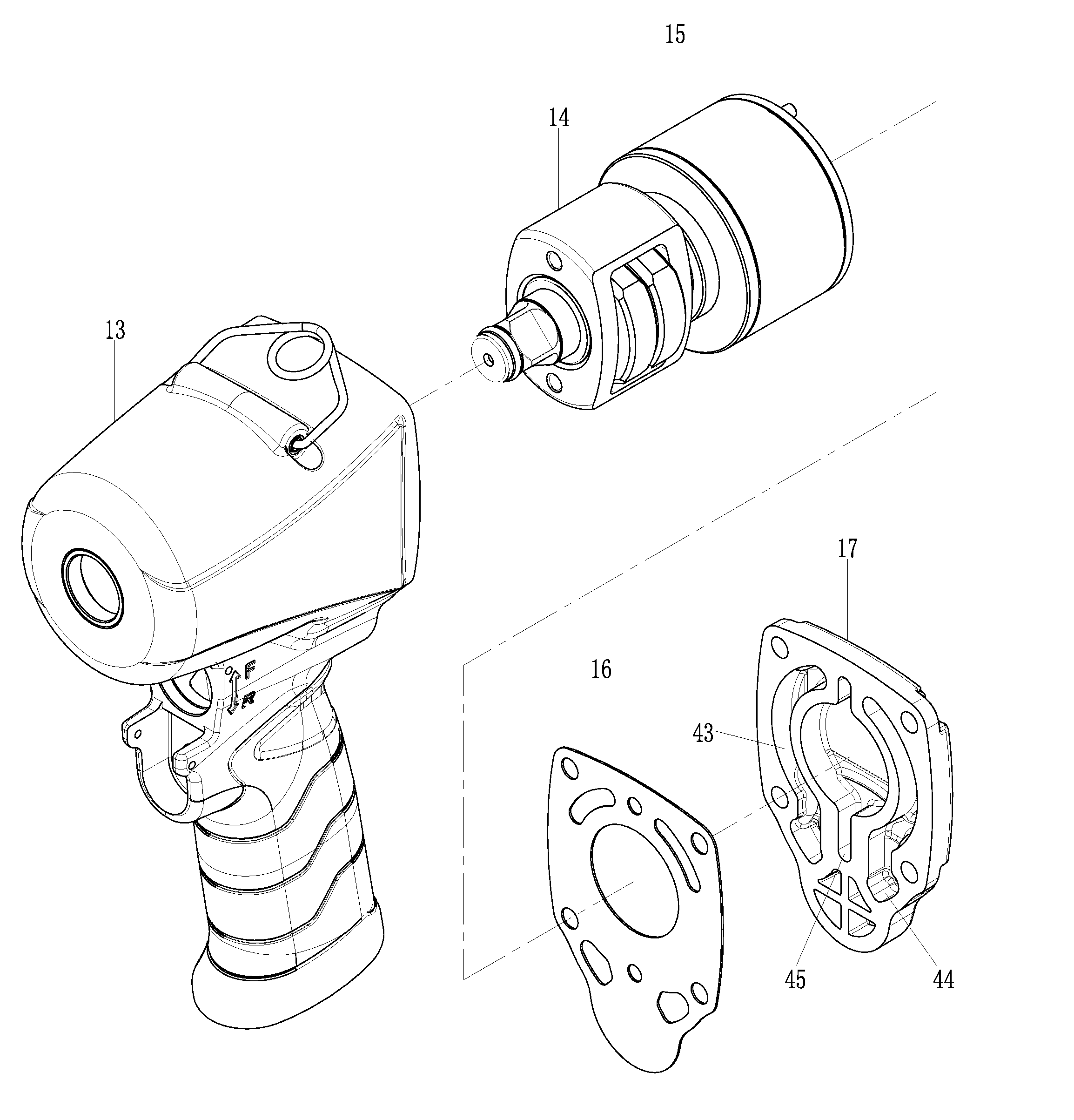
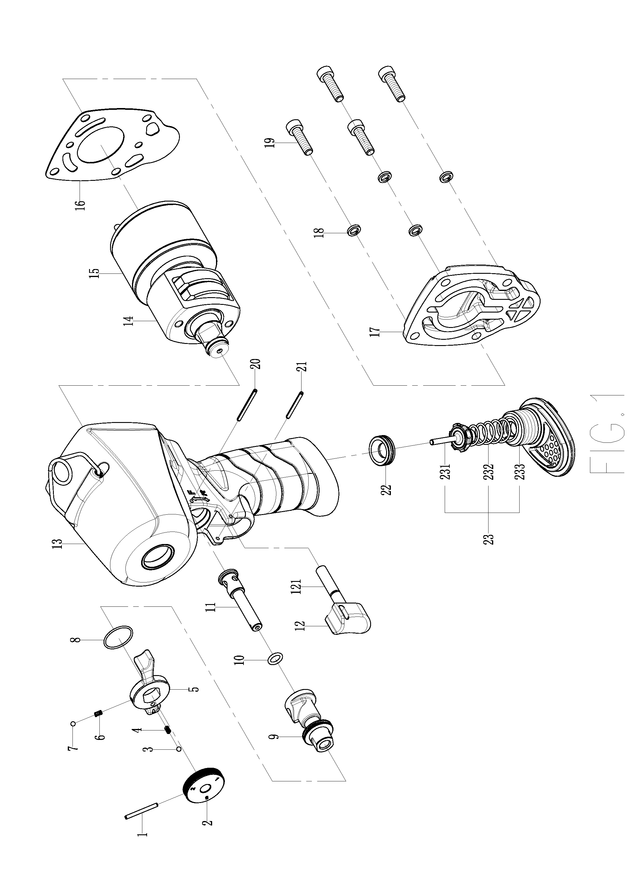
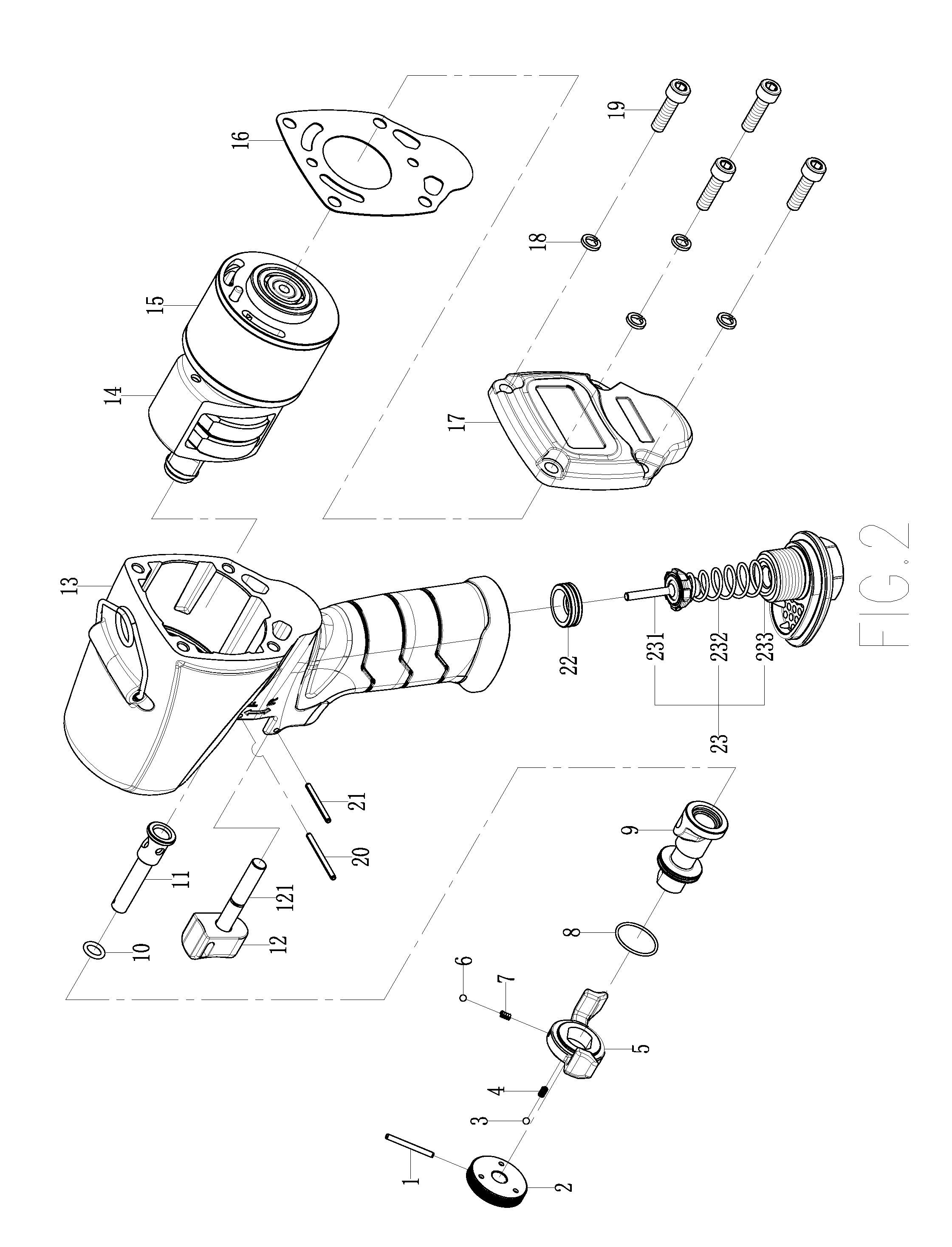
[0049]With reference to FIGS. 1 to 22 for a pneumatic wrench with a butterfly steering switching mechanism in accordance with the present invention, the pneumatic wrench comprises a casing 13, a striking module 14, a motor module 15, a back cover 17, a back cover paper pad 16, an air seal module 23, an air seal washer 22, a forward / reverse speed control assembly, a trigger module 12, a hollow pin C21, a plurality of screws 19, and a plurality of spring washers 18. A handle air intake hole 24 is formed at the bottom of the casing 13, and an air seal washer 22 is pressed into the handle air intake hole 24, and an air seal m...


PUM


Abstract

A pneumatic wrench with a butterfly steering switching mechanism includes a casing, a striking module, a motor module, a back cover, a butterfly operating lever, a speed control knob, a flow control valve, a forward/reverse rotary valve, a trigger module, and an air seal module. The novel design of the butterfly operating lever, the alternate installation of each mechanism of the wrench, and the optimal configuration of the air passage provide a wrench that can be operated by one hand for left and right handed operator and achieve the effects of lowering the production cost of a casing blank, improving the transmission loss compressed air in the wrench, and saving energy.

Description

[0001]The current application claims a foreign priority to the patent application of Taiwan No. 104207363 filed on May 13, 2015.FIELD OF THE INVENTION[0002]The present invention relates to the field of a pneumatic wrench, in particular to the pneumatic wrench with a butterfly steering switching mechanism.BACKGROUND OF THE INVENTION[0003]According to the working principle of a pneumatic wrench, compressed air is passed through an air seal mechanism, a speed control mechanism, and a forward / reverse mechanism and pushed into a cylinder to drive a vane to rotate a rotor, so as to generate high-power alternating impact loads instantaneously from a striking mechanism. With the features of large torque output and excellent safety, the pneumatic wrench is used extensively for installing and removing screws at assembly and product lines and maintenance and repair sites.[0004]The conventional pneumatic wrench is generally divided into following two types: 1. A speed-control pneumatic wrench h...

Claims


Application Information

Patent Timeline
Patent Type & Authority Applications(United States)
IPC IPC(8): B25B21/02B25F5/02B25F5/00
CPCB25B21/02B25F5/02B25F5/001B25B21/00
Inventor CHEN, CHI-CHEN
Owner YEAR CONGRATULATE INDAL
Why Eureka
Try Eureka