

Method of manufacturing pneumatic tire, shaping device and pneumatic tire
- Summary
- Abstract
- Description
- Claims
- Application Information
AI Technical Summary
Benefits of technology
Problems solved by technology
Method used
Image

Examples
first embodiment
[0034]Hereinafter, an embodiment according to the present invention is described with reference to attached drawings. The description made hereinafter is provided substantially for merely exemplifying the present invention, and the description does not intend to limit the present invention, a product to which the present invention is applied or the use of the product. Further, drawings are schematic drawings, and ratios between the respective sizes may differ from actual corresponding ratios and the like.
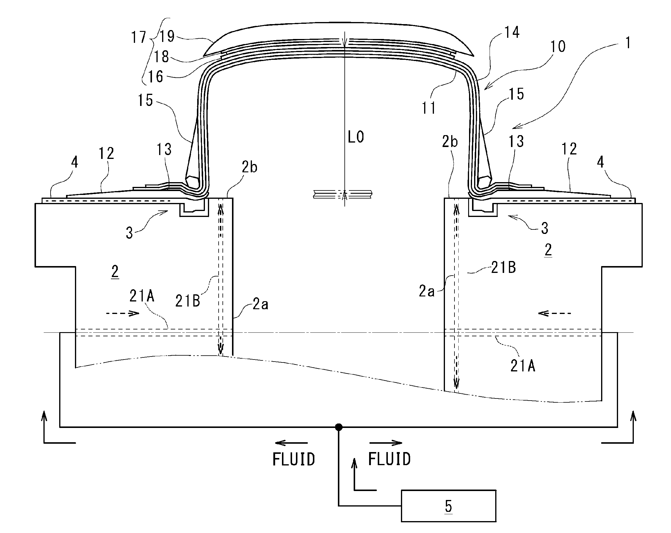
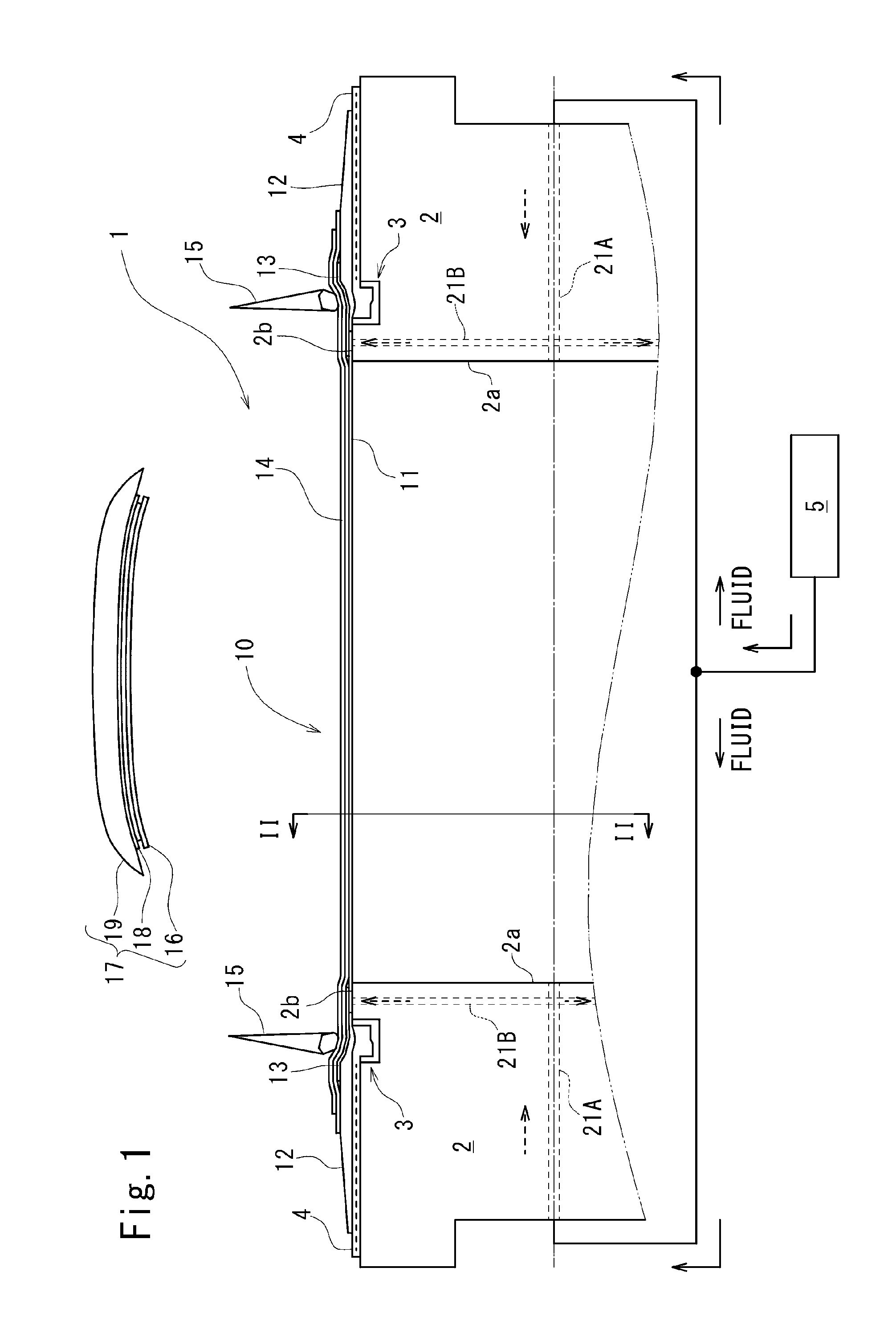
[0035]FIG. 1 shows a schematic configuration of a shaping device 1 according to one embodiment of the present invention. In FIG. 1, a cross section of a green case 10 before shaping is applied to the green case 10 and a cross section of a tread ring 17 are shown together. The shaping device 1 includes: a pair of shaping drums 2 which faces each other in an opposed manner with a predetermined distance therebetween in an axial direction, and a fluid supply part 5 connected to the shap...
second embodiment
[0063]A second embodiment differs from the first embodiment only with respect to a pressure profile of a supply pressure P1, and other configurations in the second embodiment are equal to the corresponding configurations in the first embodiment. In the second embodiment, a pressure profile is set such that a pre-shaping pressure P11A is equal to a first shaping pressure P12A. To be more specific, as shown in FIG. 7, the pre-shaping pressure P11A and the first shaping pressure P12A are equal. To be more specific, the pre-shaping pressure P11A and the first shaping pressure P12A are set to a pressure slightly lower than the first shaping pressure P12 according to the first embodiment.
[0064]By setting the pre-shaping pressure P11A and the first shaping pressure P12A equal, the green case 10 can be expanded more gently from a pre-shaping step and hence, irregularities in cord openings between the carcass cords in the carcass ply 14 can be further easily suppressed.
[0065]Besides the abov...
first reference embodiment
[0068]In a first reference embodiment, a pressure profile is set such that a first shaping pressure P12D and a second shaping pressure P13 are equal. In such a case, as shown in FIG. 10, a case internal pressure P2 in a green case 10 is gradually increased without causing an overshoot and hence, the green case 10 can be uniformly expanded. Accordingly, irregularities in cord openings between the carcass ply 14 can be easily suppressed.
PUM
| Property | Measurement | Unit |
|---|---|---|
| Pressure | aaaaa | aaaaa |
| Shape | aaaaa | aaaaa |
Abstract
Description
Claims
Application Information