Fluid Container, Check Valve Thereof and Manufacturing Method Therefor

Inactive Publication Date: 2017-02-16
ZHANG JIAYING +1
View PDF4 Cites 3 Cited by
  • Summary
  • Abstract
  • Description
  • Claims
  • Application Information

AI Technical Summary

Benefits of technology

[0015]Another advantage of the invention is to provide a fluid container and a check valve thereof, wherein the fluid container can be implemented as a device for storing various kinds of fluids, such as gas or liquid. Via the self-adhesive checking effect of the check valve, the gas or liquid is retained in a fluid storing cell of the fluid container to prevent the gas or the liquid from spilling out.
[0016]Another advantage of the invention is to provide a fluid container and a check valve thereof, wherein two fluid storing films outside the check valve are not extended to the position of the main channel, so that it is not necessary to heat-sealing the outer film together with the adjacent inner film as the prior art, so the manufacturing process is much simpler.
[0017]Another advantage of the invention is to provide a fluid container and a check valve thereof, wherein since there is only one valve film on the two sides of the main channel respectively, while filing fluid or after fluid enters into the main channel, two valve film can expanded easily, so as to open entering openings of fluid filling channels, through which the fluid enters into each flu

Problems solved by technology

However, the packaging method of this kind of traditional packaging boxes does not provide any anti-impact or anti-collision function, and also does not prevent any damage when the packaging boxes fall off.
In other words, during being transported and stored, the packaging boxes are usually thrown from here to there, and may result in the deformation of the packaging boxes, and this may further lead to the damaging or deformation of the packaged items.
However, the cost of transporting and storing is expensive during transporting the packaging boxes and the filled cushioning materials.
On the other hand, the cushioning foam materials pollute the enviro

Method used


Image

  • Fluid Container, Check Valve Thereof and Manufacturing Method Therefor
  • Fluid Container, Check Valve Thereof and Manufacturing Method Therefor
  • Fluid Container, Check Valve Thereof and Manufacturing Method Therefor

Examples


Example

[0091]The following description is disclosed to enable any person skilled in the art to make and use the present invention. Preferred embodiments are provided in the following description only as examples and modifications will be apparent to those skilled in the art. The general principles defined in the following description would be applied to other embodiments, alternatives, modifications, equivalents, and applications without departing from the spirit and scope of the present invention.

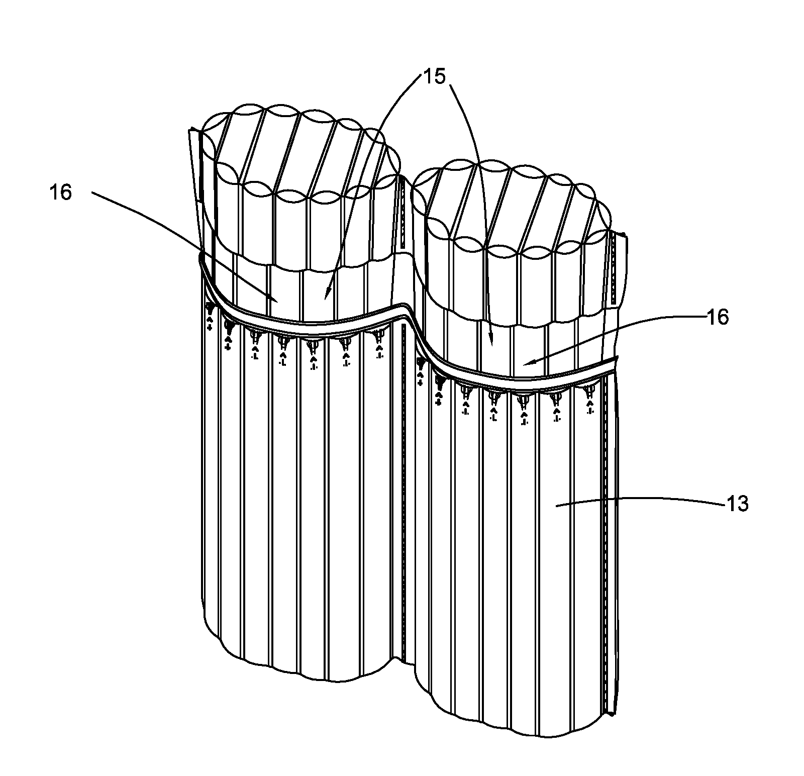
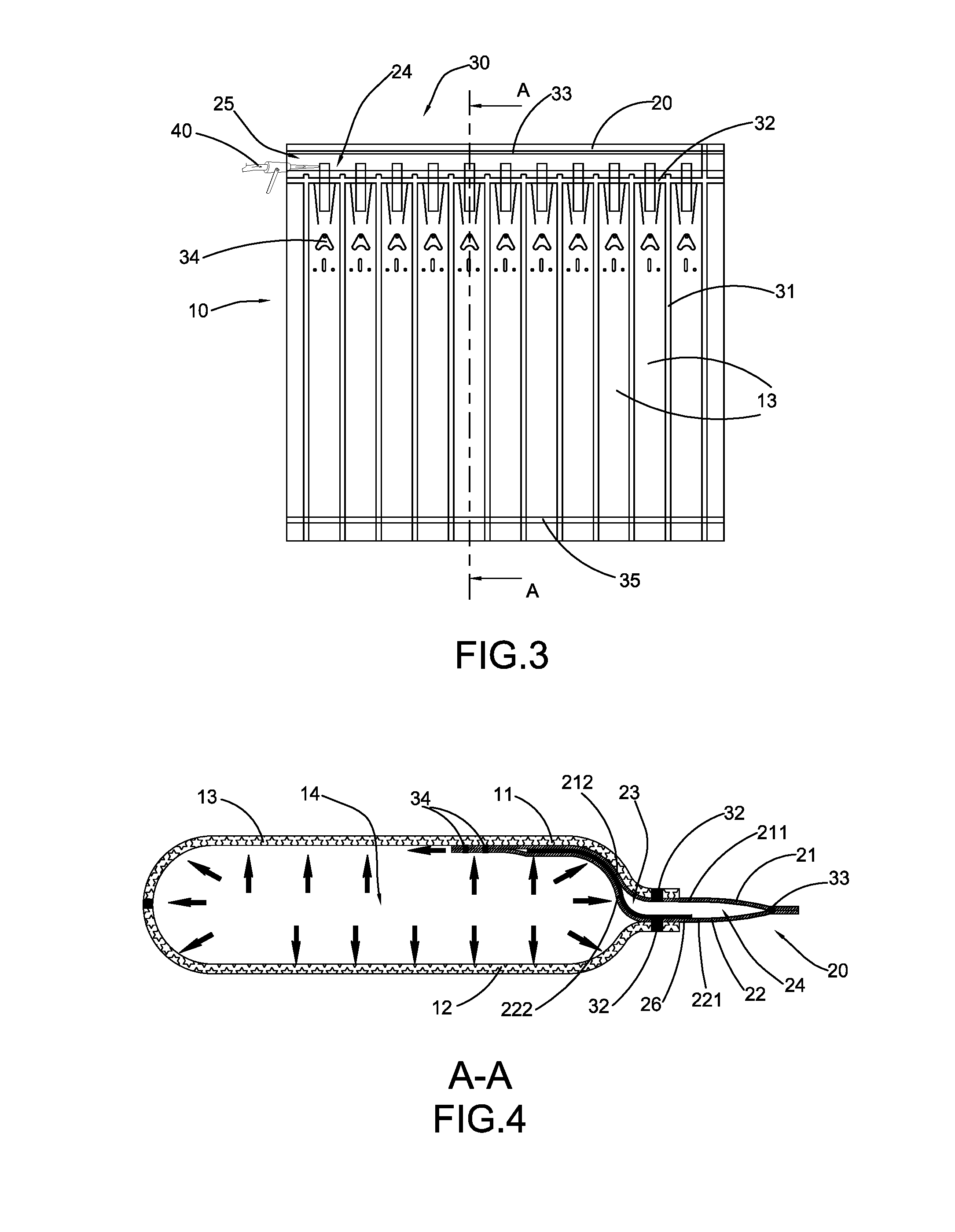
[0092]FIGS. 3 to 7 of the drawings illustrate a fluid container according to a first preferred embodiment of the present invention, wherein the fluid container is embodied as an air packaging arrangement. The air packaging arrangement has an inflatable structure, so as to provide air cushioning effect, after being inflated, for various kinds of packaged items, such as electronic products, food, medicine products, chemical materials, biological materials, plastics, ceramics, and fast moving consum...


PUM


Abstract

A fluid container includes a fluid storing main body and at least one check valve. The fluid storing main body includes two fluid storing films overlapping with each other, to form at least one fluid storing cell having a fluid storing chamber. The check valve includes two valve films overlapping with each other. Each valve film has outer and inner extending portions integrated formed with each other. The two inner extending portions and the fluid storing films overlap with each other and are connected between the two inner extending portions to form a fluid filling channel, so as to fill fluid to the fluid storing chamber of each fluid storing cell via the fluid filling channel. After the fluid filling is finished, the pressure of the fluid storing chamber acts on the two valve films to close the fluid filling channel, so as to avoid fluid leakage.

Description

CROSS REFERENCE OF RELATED APPLICATION[0001]This is a non-provisional application that claims priority to International Application Number PCT / CN2015 / 098899, international filing date Dec. 25, 2015, which claims priority to Chinese application number CN201410853968.9, filed on Dec. 31, 2014 and Chinese application number CN201510299507.6, filed on Jun. 3, 2015, the entire contents of each of which are expressly incorporated herein by reference.NOTICE OF COPYRIGHT[0002]A portion of the disclosure of this patent document contains material which is subject to copyright protection. The copyright owner has no objection to any reproduction by anyone of the patent disclosure, as it appears in the United States Patent and Trademark Office patent files or records, but otherwise reserves all copyright rights whatsoever.BACKGROUND OF THE PRESENT INVENTION[0003]Field of Invention[0004]The present invention relates to a fluid containing device, and more particularly to a fluid container having a...

Claims


Application Information

Patent Timeline
IPC IPC(8): F16K27/00F16K31/12B65D81/05F16K15/20
CPCF16K27/003B65D81/052F16K31/12F16K15/202B65D81/03F16K15/147F16K15/20
Inventor NIE, HUIPING
Owner ZHANG JIAYING
Why Eureka
Try Eureka