
Method and device for partial maintenance of a hydraulic circuit

a hydraulic circuit and partial maintenance technology, applied in the field of printers, can solve problems such as difficulty in supplying ink, complete blockage, formation of dry ink plugs,

Active Publication Date: 2016-11-17
DOVER EURO SARL
View PDF2 Cites 12 Cited by
  • Summary
  • Abstract
  • Description
  • Claims
  • Application Information

AI Technical Summary

Benefits of technology

The patent text describes a type of printer called a continuous inkjet (CU) printer, which is used for industrial coding and marking. The printer has several subassemblies, including an ink circuit, a controller, and an interface for the operator. The ink circuit supplies ink to the printer head under pressure and manages ink output from the jets. The printer head has a drop generator that emits ink drops that can be directed towards printing or recovery. The printer can also have a negative pressure to recover unused ink. The patent text describes various functions of the printer, such as rinsing the head and replacing limited life components. The technical effects of the patent text are related to the architecture and operation of CU printers, and how to prevent blockages and other issues during use.

Problems solved by technology

The consequences of this sedimentation may be the formation of solid plugs in these conduits, that can partially or completely block them.
Furthermore, during essential maintenance operations, exposing connections to air in the presence of ink can cause the formation of dry ink plugs.
The same problem also arises with the connection cannula between the ink cartridge and the ink circuit; ink is supplied to the circuit from a cartridge that is a consumable element that the user replaces when it is empty.
The main result is difficulties in supplying ink and loss of opaqueness of the markings.
These problems are critical and action by a technician is necessary because ink cannot be stirred when it is in the connection ducts and means; the printer is then blocked and production is stopped, which means that the user is discontented and there is a resulting loss of time and extra costs.
In the specific field of inkjet printers, there is no known technique for solving these connection blockage problems, particularly in the cannula or in conduits or in pipes in which ink circulates.
Moreover, some parts of the circuit may require cleaning (particularly if blocking problems like that mentioned above occur), without other parts of the circuit being concerned by this problem.
This operation takes a long time, requires a total shutdown of the machine and causes higher solvent consumption than is necessary.
In general, consumables used in this type of device and particularly the solvent, are expensive elements.
Therefore, the problem arises of creating an ink circuit and a functioning method for an ink circuit, by which it is possible to optimise cleaning of the hydraulic connections in an optimum and appropriate manner, particularly in the case of a pigment ink.
The same problem arises for any ink, even if it is not a pigment ink, that can dry and form deposits of dry material in the conduits and connections of the ink circuit.

Method used


Image

  • Method and device for partial maintenance of a hydraulic circuit
  • Method and device for partial maintenance of a hydraulic circuit
  • Method and device for partial maintenance of a hydraulic circuit

Examples


Embodiment Construction

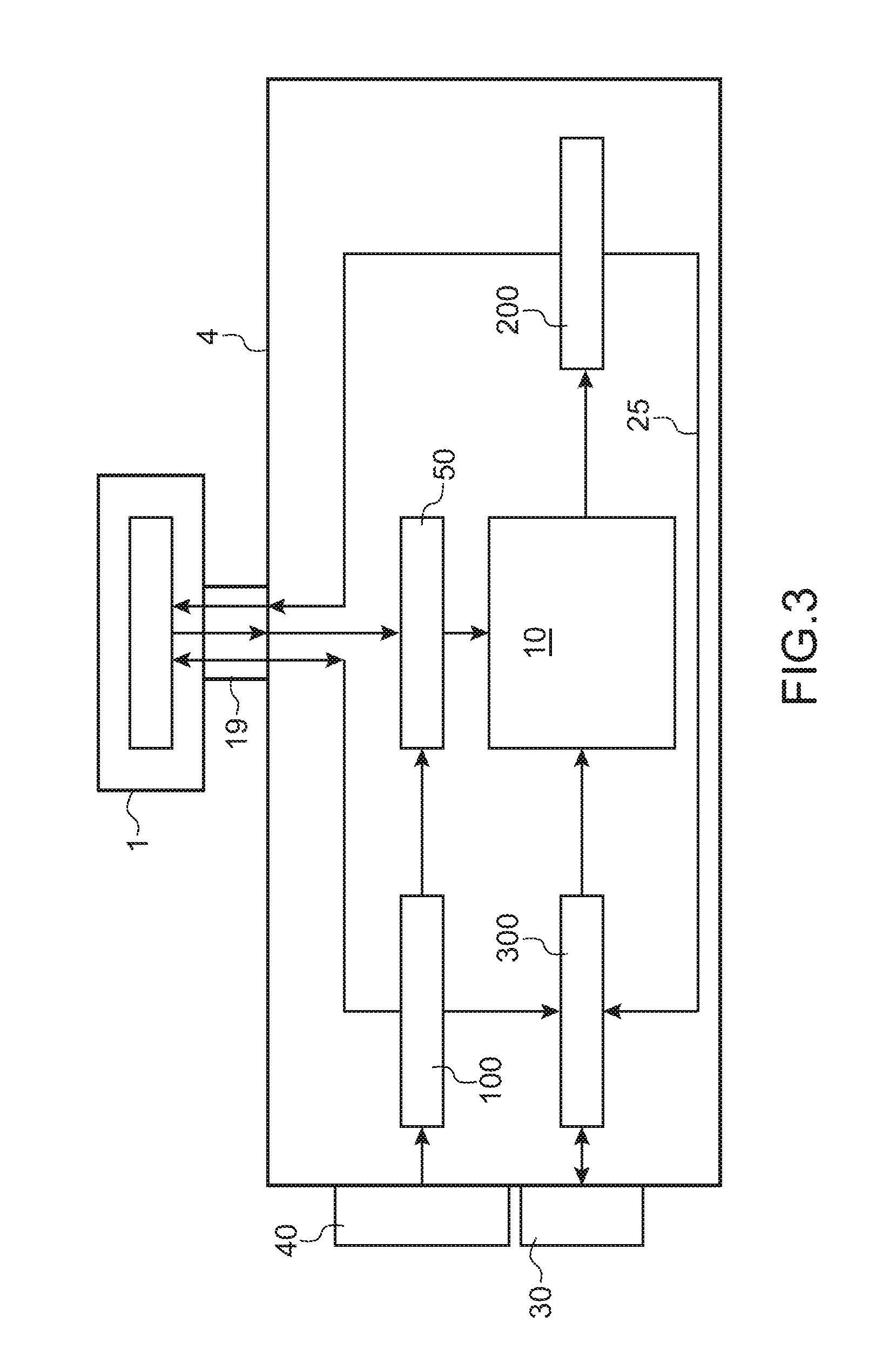
[0096]One example of an architecture of the fluid circuit of a printer according to the invention, or in which the invention can be applied, is shown in FIG. 3 on which references identical to those used above denote identical or corresponding elements. In particular, there is the flexible umbilical 19 that contains all hydraulic and electrical connections to the print head 1, to which the printer architecture described below can be related.

[0097]A fluid recovery circuit or means 50 according to the invention will be described below.

[0098]A fluid storage and transfer circuit or means 100 according to the invention will be described below.

[0099]We shall start by describing a fluid circuit 4 to which at least one of the circuits according to the invention may be applied, in FIG. 3.

[0100]FIG. 3 shows that the fluid circuit 4 of the printer comprises a plurality of means 10, 50, 100, 200, 300, each means being associated with a specific function. A removable ink cartridge 30 and a solve...


PUM


Abstract

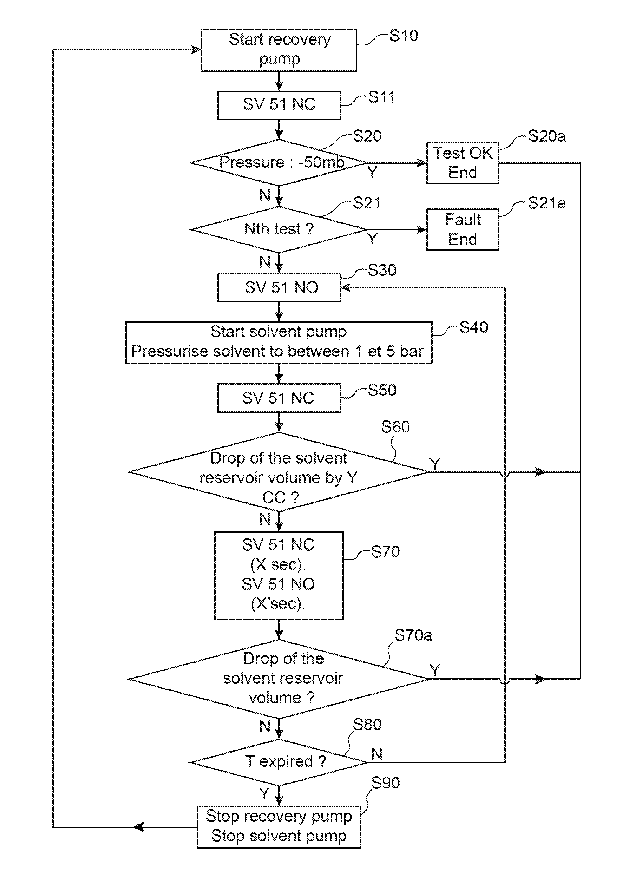
The invention relates to a method of cleaning a fluid circuit in an inkjet printer that comprises a print head connected to the fluid circuit through an umbilical (19), and also comprises means (50) of recovering fluid from the print head (1), this method comprising at least sending solvent to said fluid recovery means (50), without making this solvent flow in the umbilical or in the print head.

Description

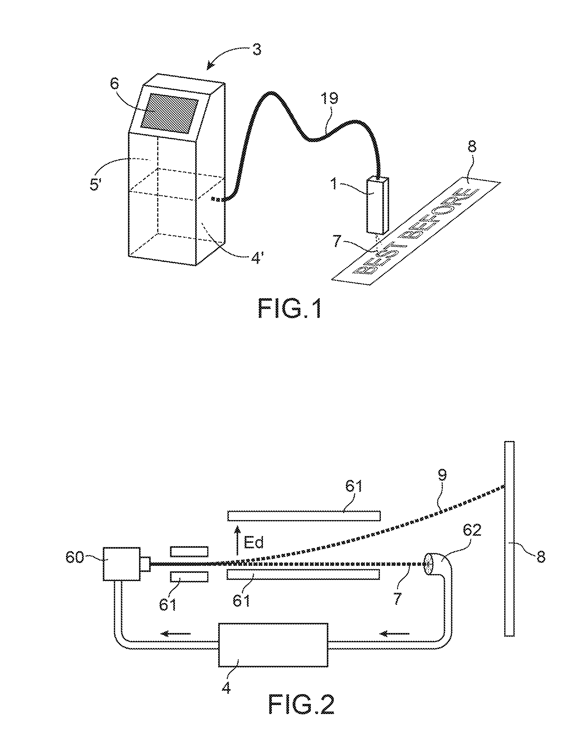
TECHNICAL DOMAIN AND PRIOR ART[0001]The invention relates to the field of printers, and particularly continuous inkjet (CU) type printers.[0002]It also relates to the architecture (the layout of the Ink circuit) of a printer, for example of the CIJ type, and particularly to prevent situations in which some channels along which ink passes can become blocked during use.[0003]Continuous inkjet (CIJ) printers are well known in the field of industrial coding and marking of miscellaneous products, for example for marking barcodes, Best Before dates on food products or references or distance marks on cables or pipes directly on the production line at high speed. This type of printer is also used in some decoration fields in which the possibilities of industrial graphic printing are used.[0004]These printers have several typical subassemblies, as shown in FIG. 1.[0005]Firstly, a print head 1, used usually offset from the body of the printer 3, is connected to it through a flexible umbilical...

Claims


Application Information

Patent Timeline
Patent Type & Authority Applications(United States)
IPC IPC(8): B41J2/165
CPCB41J2/16552B41J2/01B41J2/1707B41J2/17563B41J2/17596B41J2/18B41J2/185B41J29/17B41J2002/16594B41J2002/1853
Inventor POURTIER, FRANCIS
Owner DOVER EURO SARL
Learn More