System and method for determining drill string motions using acceleration data

a technology of acceleration data and drill string, applied in the field of hydrocarbon drilling, can solve the problems of excessive torque, significant wear of drill string, component failure, etc., and achieve the effect of reducing drilling vibration and better understanding of drill string dysfunction

Active Publication Date: 2016-11-17
CONOCOPHILLIPS CO
View PDF5 Cites 106 Cited by
  • Summary
  • Abstract
  • Description
  • Claims
  • Application Information

AI Technical Summary

Benefits of technology

[0008]The present disclosure addresses limitations in the art by providing a system and method for mapping three orthogonal accelerations into motions of the drill string, providing a 2D / 3D visualization of how the drill string deviates from the ideal drilling condition. Since the drilling vibration causes the drill string to deviate from ideal, uniform circular rotations, the mapping of the non-uniform rotations of the drill string leads to a better understanding of the dynamics of drill-string dysfunctions. The present invention calls for using measured acceleration data to map the positions of drill-string motions continuously and produces various attributes to quantify the drilling dysfunctions. 2D and 3D visualizations of various dysfunction attributes describes how the vibration affects the drill-string motions. When combined with other information, it may be used to reduce drilling vibration.
[0009]The present invention enables the development of efficient and robust workflows for controlling and optimizing well drilling operations in real time. Dysfunctions are critical for proactively detecting events that may lead to equipment failures. In the particular case of real time drilling, results should aid at improving rate of penetration and minimizing well bit failures. Extensions of the present invention could be oriented to impact any automated activity that require an efficient way to determine dysfunctions in real time signals as produced by sensors, satellite and other mobile devices.

Problems solved by technology

Resistance encountered by the drill string in a wellbore during drilling causes significant wear on the drill string, especially the drill bit and the BHA.
Various conditions referred to as drilling dysfunctions that may lead to component failure include excessive torque, shocks, bit bounce, induced vibrations, bit whirl, stick-slip, among others.
These conditions must be rapidly detected so that mitigation efforts are undertaken as quickly as possible, since some dysfunctions can quickly lead to tool failures.
It does not provide any insight how the drill string moves around the borehole.

Method used


Image

  • System and method for determining drill string motions using acceleration data
  • System and method for determining drill string motions using acceleration data
  • System and method for determining drill string motions using acceleration data

Examples


examples

[0046]FIGS. 3-8 illustrate two examples of the present invention by illustrating, or mapping, irregular drill string motions due to vibration.

[0047]The first data example (Permian ISUB) utilized the following data sources:

[0048]Sample rate=100 Hz

[0049]Axial Vibration

[0050]Down-hole RPM

[0051]Polar radial Vibration

[0052]Polar tangential Vibration

[0053]Hole Depth

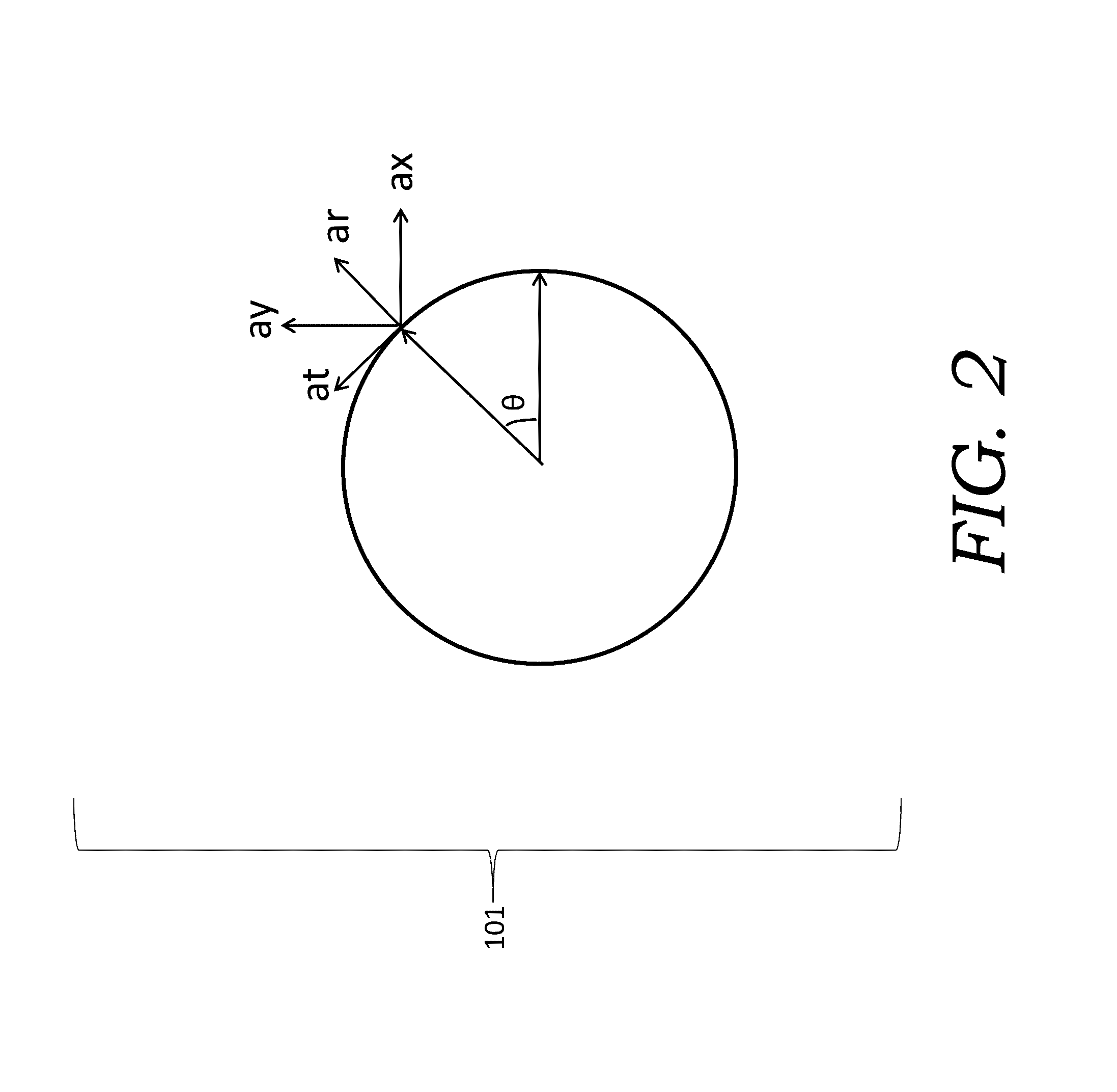
[0054]Turning to FIG. 3, input data is presented, including data channel 1—axial vibration 301, representing axial acceleration; data channel 2—down-hole rotations per minute (RPM) 302; data channel 3—polar radial vibration 303, representing the polar coordinates of radial acceleration; and data channel 4—labelled as polar tangential vibration 304, represent the polar coordinates of tangential acceleration. Data channel 5 presents measured hole depth 305.

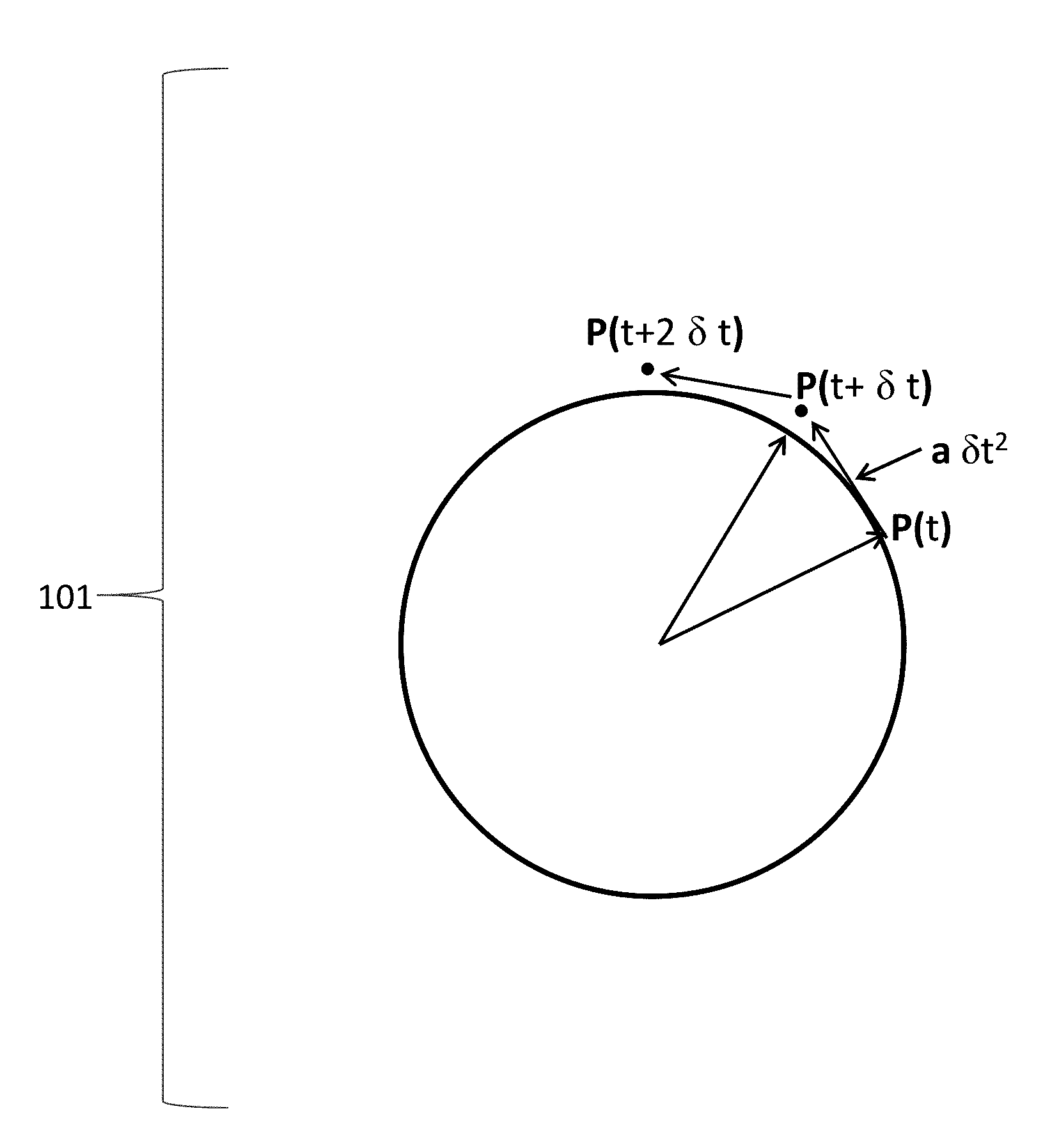
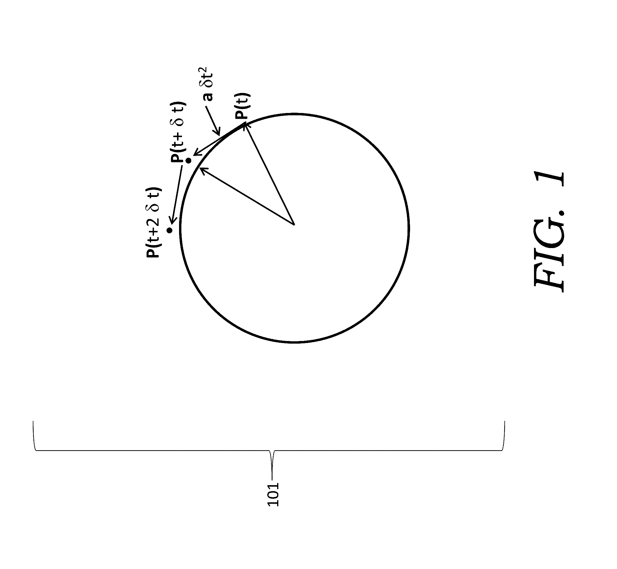
[0055]The mapping of tri-axial accelerations into drill-string motions consists of 3 key steps: (1) it approximates the gravitational and centripetal accelerations by a local r...


PUM


Abstract

Systems and methods compute dysfunctions via mapping of tri-axial accelerations of drill pipe into drill-string motions. The methods remove gravitational and centripetal accelerations to yield corrected acceleration data due to the vibration only, transform the corrected acceleration data, and maps resulting transformed acceleration data into continuous drill-string positions. The maps provide 2D / 3D visualization of drill-string motions to enable real-time optimization and control of well drilling operations and other scenarios where proactive detection of temporal events in automated systems may aid in avoiding failures.

Description

CROSS-REFERENCE TO RELATED APPLICATIONS[0001]This application is a non-provisional application which claims benefit under 35 USC §119(e) to U.S. Provisional Application Ser. No. 62 / 161,370 filed May 14, 2015, entitled “SYSTEM AND METHOD FOR DETERMINING DRILL STRING MOTIONS USING ACCELERATION DATA,” which is incorporated herein in its entirety.STATEMENT REGARDING FEDERALLY SPONSORED RESEARCH OR DEVELOPMENT[0002]None.FIELD OF THE INVENTION[0003]The present disclosure relates in general to the field of hydrocarbon drilling. More particularly, but not by way of limitation, embodiments of the present invention relate to a system and method transforming acceleration data to drill-string motions related to drilling dysfunctions.BACKGROUND OF THE INVENTION[0004]Hydrocarbon reservoirs are developed with drilling operations using a drill bit associated with a drill string rotated from the surface or using a downhole motor, or both using a downhole motor and also rotating the string from the s...

Claims


Application Information

Patent Timeline
Patent Type & Authority Applications(United States)
IPC IPC(8): G01M99/00E21B47/04E21B45/00E21B47/12
CPCG01M99/008E21B45/00E21B47/04E21B47/12E21B44/00E21B47/09
Inventor CHIU, STEPHEN K.ANNO, PHIL D.
Owner CONOCOPHILLIPS CO
Why Eureka
Try Eureka