
Method and system for processing acoustic waveforms

a waveform and processing method technology, applied in the field of acoustic well logging, can solve the problems of inability to meet the requirements of large-scale computing, large computational requirements, and irregular boreholes, and achieve the effect of improving the quality of results

Inactive Publication Date: 2016-11-17
SCHLUMBERGER TECH CORP
View PDF3 Cites 7 Cited by
  • Summary
  • Abstract
  • Description
  • Claims
  • Application Information

AI Technical Summary

Benefits of technology

The patent describes a system that can adjust the properties of its acoustic tools based on the conditions in which it is logging (such as the frequency of the transducers) and can also optimize the software parameters used to process the results (such as the frequency of applied filters). This helps to improve the quality of the results and make the data more accurate.

Problems solved by technology

A challenge for processing acoustic data is how to correctly handle the dispersion effect of the waveform data.
The limitation is that they require a circular borehole and are not available for anisotropic or irregular formations.
The problem of these methods is heavy computational requirements.
However, practical processing, which includes the step of comparing the measured data with the modeled dispersion curves is currently limited to isotropic or TIV formations and borehole with circular cross-sections.
Performing this step for other types of anisotropic formations (general anisotropy) or borehole with non-circular and nonconcentric cross section is impractical because either the accuracy is not always sufficient or controllable (perturbation theory approach, etc.) or the computation time is prohibitively large (full 3D wavefield modeling, etc.).
At the moment, it is not possible to do by any other means with acceptable accuracy and speed.
As a result, it is drastic change in the capabilities of the existing process and makes for the whole new process.

Method used


Image

  • Method and system for processing acoustic waveforms
  • Method and system for processing acoustic waveforms
  • Method and system for processing acoustic waveforms

Examples


Embodiment Construction

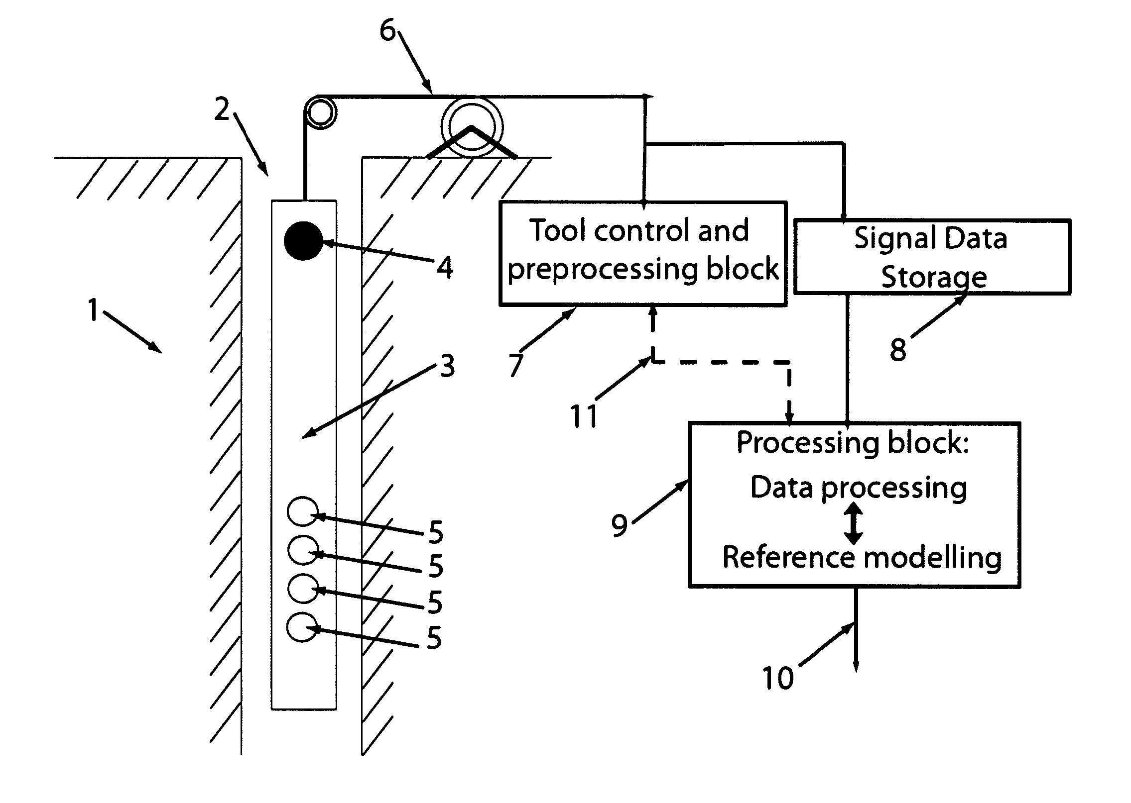
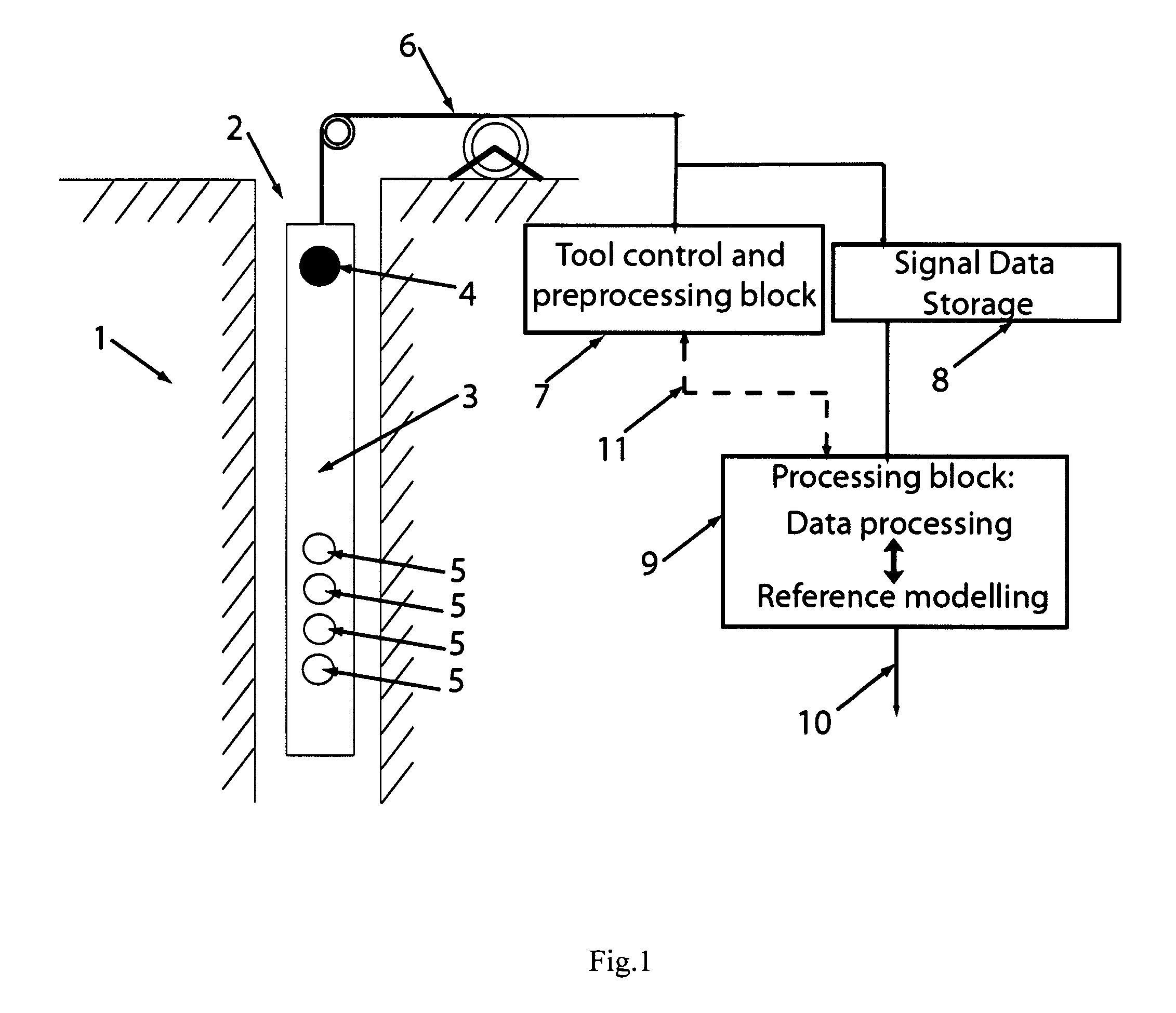
[0012]FIG. 1 shows the general illustration of the measurement by logging tool in a borehole and processing outside it. To study physical properties of a subterranean formation 1 one may drill a borehole 2, which traverses the formation 1. The formation may be inhomogeneous and anisotropic, while the borehole can have a noncircular shape of cross section. In acoustic logging, a tool 3 is lowered into the borehole and acoustic energy is transmitted from transducers 4 into the borehole and the formation. The acoustic waves that travel in the formation are then detected with an array of receivers 5. To push or pull the tool inside the formation 1 and to control its depth a logging / data cable 6 is often used. Through this cable the information about the acoustic signals, measured by the array of receivers 5 can be acquired. This data may flow to a tool control block 7 or to a data storage 8 device. The main goal of the block 7 is to control the tool and environment in the borehole 2 (e....


PUM


Abstract

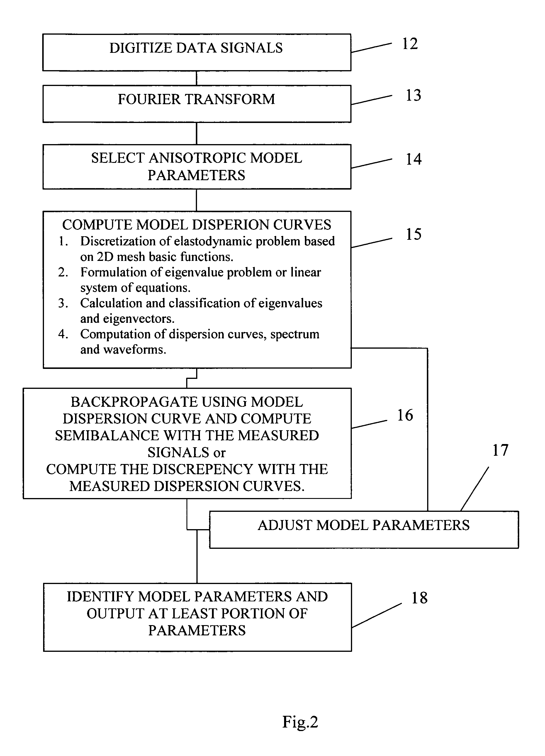
Method for processing acoustic waveforms comprises acquiring acoustic waveforms in a borehole traversing a subterranean formation and transforming at least a portion of the acoustic waveforms to produce frequency domain signals. Then model dispersion curves, modes spectrum or waveforms are generated based on an anisotropic borehole-formation model having a set of anisotropic and geometrical borehole-formation parameters and by specifying governing equations and computational mesh based functional basis. The frequency-domain signals are back-propagating using the model dispersion curves to correct dispersiveness of the signals and coherence of the back-propagated signals is calculated. Alternatively the difference between the measured and the model dispersion curves is determined. Model parameters are iteratively adjusted until the coherence reaches a maximum or exceeds a selected value, or alternatively until the difference between the measured and the model dispersion curves becomes minimal or is reduced to below a selected value. Then at least a portion of the set of anisotropic and geometrical borehole-formation parameters is obtained.

Description

FIELD OF THE INVENTION[0001]The invention relates generally to acoustic well logging. More particularly, this invention relates to acoustic well logging techniques useful in determining formation properties.BACKGROUND OF THE INVENTION[0002]In acoustic logging, a tool is lowered into a borehole and acoustic energy is transmitted from a source into the borehole and the formation. The acoustic waves that travel in the formation are then detected with an array of receivers. These waves are dispersive in nature, i.e. the phase slowness is a function of frequency. This function characterizes the wave and is referred to as a dispersion curve or mode's spectrum. A challenge for processing acoustic data is how to correctly handle the dispersion effect of the waveform data.[0003]Important step in processing acoustic logging data is dispersion or modes' spectral analysis, that is, its optimal decomposition in limited number of modes in frequency-wavenumber domain, for example, based on Prony's...

Claims


Application Information

Patent Timeline
IPC IPC(8): G01V1/48
CPCG01V1/48G01V2210/582G01V2210/586G01V2210/6242
Inventor SYRESIN, DENIS EVGENIEVICHZHARNIKOV, TIMUR VYACHESLAVOVICHFUKUHARA, MASAFUMIENDO, TAKESHIYAMAMOTO, HIROAKI
Owner SCHLUMBERGER TECH CORP
Learn More