Switch unit and game machine

a technology of switch unit and game machine, which is applied in the direction of mechanical equipment, lighting and heating equipment, instruments, etc., can solve the problems of reducing the degree of perfection of the performance, so as to reduce the light leakage in the light performance without increasing the number of parts or complicating the process flow. , to achieve the effect of reducing the number of parts and reducing the degree of impact of the display performan

Active Publication Date: 2016-11-17
ORMON CORP
View PDF6 Cites 8 Cited by
  • Summary
  • Abstract
  • Description
  • Claims
  • Application Information

AI Technical Summary

Benefits of technology

[0022]According to the present invention, the effect of being able to provide a switch unit can be exerted, the switch unit being capable of making a display performance with a larger impact by displaying an image also between press buttons and on the periphery of a placement region of the press buttons, and capable of reducing light leakage in a light performance without increasing the number of parts or complicating a process flow.

Problems solved by technology

However, in this case, the rubber sheet made of a single sheet needs to be cut into pieces for the respective operation buttons, thus increasing the number of parts and complicating a process flow.
Further, the cut rubber sheet is apt to be displaced at the time of assembly.
When the displacement occurs, in the light performance of illuminating the periphery of the operation button, light leaks to the inside or the outside of the operation button to interfere with a display performance made by the display device or interfere with a light performance of the other operation button, thus leading to a decrease in degree of perfection of the performance.
As thus described, the button body is elastically transformed to achieve a pressable configuration, thus making it unnecessary to separately provide a mechanism for supporting the top surface in a pressable manner and returning the top surface to its fixed position, the mechanism impeding a display performance made by the display part.

Method used


Image

  • Switch unit and game machine
  • Switch unit and game machine
  • Switch unit and game machine

Examples


Embodiment Construction

[0035]Hereinafter, embodiments of the present invention is described with reference to the attached drawings. However, the present invention is not limited to the embodiments described below, and various design changes can be made without departing from the gist of the present invention. In embodiments of the invention, numerous specific details are set forth in order to provide a more thorough understanding of the invention. However, it will be apparent to one of ordinary skill in the art that the invention may be practiced without these specific details. In other instances, well-known features have not been described in detail to avoid obscuring the invention.

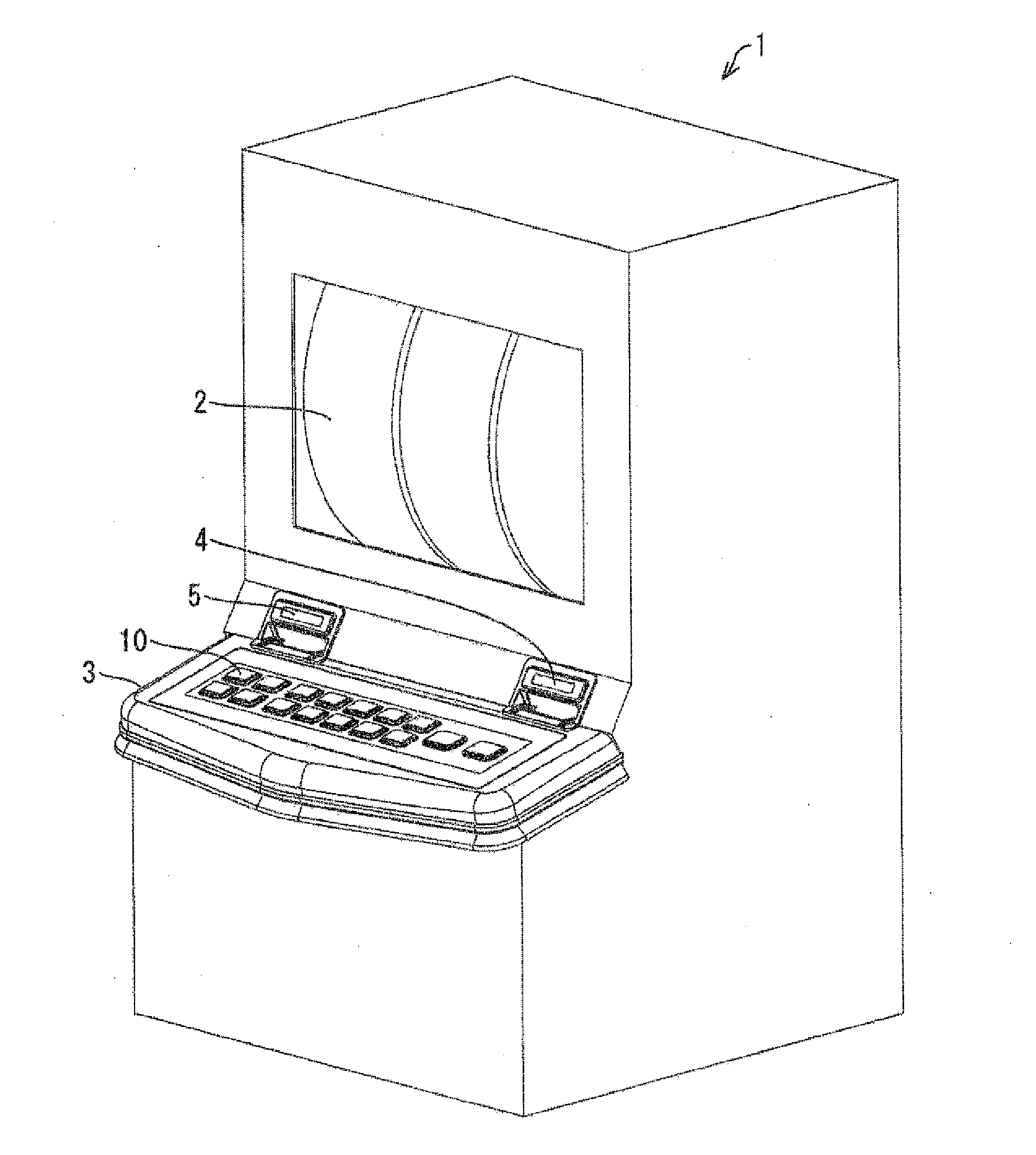
[0036]A switch unit of the present invention can be employed in operation boards of various game machines, industrial equipment, and consumer equipment. In the embodiment, a description is given of an example of mounting the switch unit in a slot machine as a game machine installed in a game hall such as a casino.

[0037]FIG. 1...


PUM


Abstract

A switch unit has a display part configured to display an image, and an operation part provided on the display part in a stacked manner. The operation part includes a plurality of press buttons each having a pressable top surface formed to be transparent, a transparent base having a plurality of openings formed so as to be spaced from each other in positions corresponding to a display region of the display part, while avoiding a peripheral edge of the display region, and a transparent substrate provided below the base and having a light source in a position corresponding to the outer periphery of the top surface. Each of the press buttons includes, and forms into a unit, a button body having the top surface, and a frame-like light guiding body provided in a flange shape below the button body and provided so as to cover the light source.

Description

CROSS-REFERENCE TO RELATED APPLICATION[0001]This application is based on Japanese Patent Application No. 2015-099495 filed with the Japan Patent Office on May 14, 2015, the entire contents of which are incorporated herein by reference.BACKGROUND[0002]1. Field[0003]The present invention relates to a switch unit, and a game machine mounted with the switch unit.[0004]2. Related Art[0005]There has hitherto been a game machine, what is called a slot machine. In the slot machine, a plurality of reels displaying a plurality of types of symbols are spun. A winning combination is determined based on a matching pattern of symbols and the matched symbols which are displayed in a window when the reels stop. A prize is given to a player in accordance with the winning combination and the number of bets. Input of the number of bets, instruction to start spinning of the reels, and some other operation are performed using an operation board provided in the front of the slot machine.[0006]This type o...

Claims


Application Information

Patent Timeline
Patent Type & Authority Applications(United States)
IPC IPC(8): G07F17/32F21V33/00F21V8/00
CPCG07F17/3223F21Y2101/02F21V33/008G02B6/0051G07F17/3209G07F17/3211G07F17/34G02B6/00
Inventor ONOYAMA, TAICHISUMI, MASAAKIONITSUKA, HIROYUKIAGATA, TAKEHIROKIMURA, MASATAKA
Owner ORMON CORP
Why Eureka
Try Eureka