
VERIFY SCHEME FOR ReRAM

a verification scheme and memory array technology, applied in the field of high density memory arrays, can solve the problems of less reliable devices over repeated use, and achieve the effect of less stress and more reliabl

Active Publication Date: 2016-11-17
MACRONIX INT CO LTD
View PDF2 Cites 25 Cited by
  • Summary
  • Abstract
  • Description
  • Claims
  • Application Information

AI Technical Summary

Benefits of technology

The technology allows for a more reliable and efficient programming of memory devices. It achieves this by controlling the amplitude of the pulses used for programming, reducing stress on the memory devices and increasing their reliability. Additionally, a pulse with opposite polarity to the program pulse is applied after a failed program verify operation to further improve programming accuracy.

Problems solved by technology

Such stronger operation conditions, however, stress and damage the memory element, which makes the device less reliable over repeated use.

Method used


Image

  • VERIFY SCHEME FOR ReRAM
  • VERIFY SCHEME FOR ReRAM
  • VERIFY SCHEME FOR ReRAM

Examples


Embodiment Construction

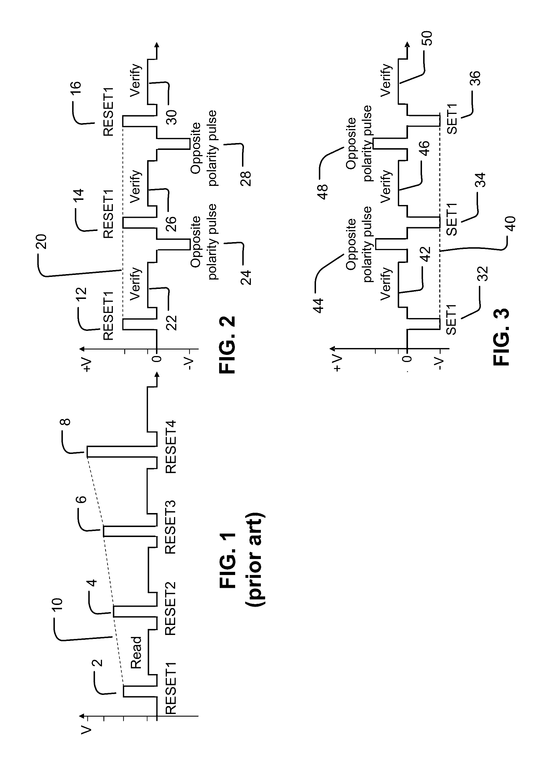
[0046]FIG. 1 is a graph of voltage versus time, showing a series of reset programming operation pulses with increasing amplitudes, in response to failed program verify operations.

[0047]A selected memory cell undergoes multiple cycles of programming reset and verify operations. In each cycle, a programming reset operation occurs, followed by a verify operation which reads the selected memory cell.

[0048]With the shown graph, four cycles of programming reset and verify operations are shown as 2, 4, 6, and 8. With each subsequent cycle, the magnitude of the programming reset pulse increases after a failed verify, to perform incremental step pulse programming (ISPP). The programming pulse names RESET1, RESET2, RESET3, and RESET4 indicate the increasing magnitudes. A positive slope trend line 10 connects the tops of the programming pulses, indicating the increasing magnitudes.

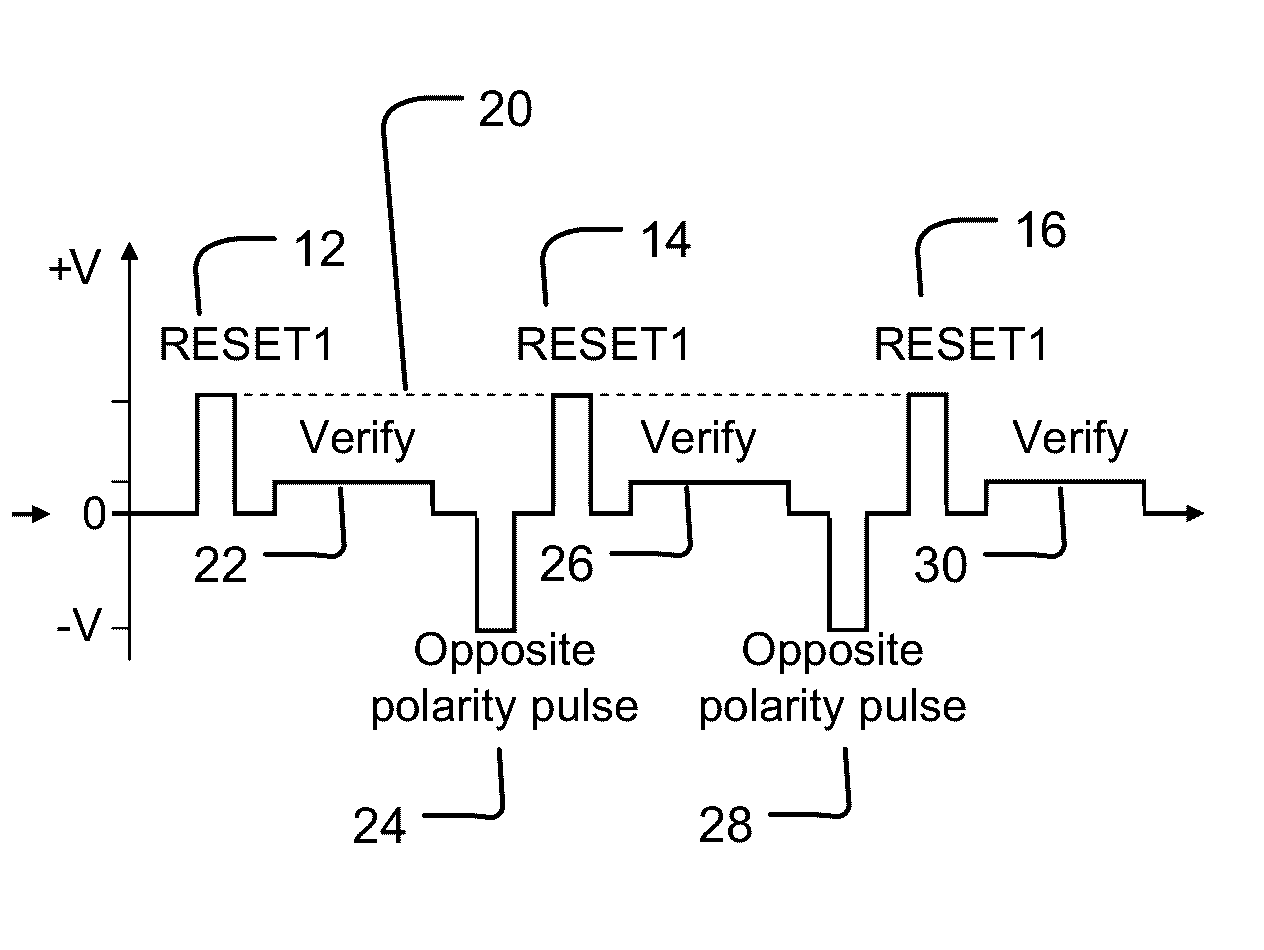
[0049]FIG. 2 is a graph of voltage versus time, showing, in response to failed program verify operations, (i) a se...


PUM


Abstract

Circuitry coupled to a programmable element comprising metal oxide is configured to execute a program-verify operation including: an initial cycle of a program operation and a verify operation, and subsequent cycles. The initial cycle includes an initial instance of the program operation to establish a cell resistance of the programmable element, and an initial instance of the verify operation to determine whether the cell resistance of the memory cell is within the target resistance range. At least one of the subsequent cycles includes an additional pulse having a second polarity to the programmable element, and a subsequent instance of the verify operation. The first polarity of the initial program pulse and the second polarity of the additional pulse have opposite polarities. A subsequent instance of the program operation includes applying a subsequent program pulse having the first polarity to the programmable element.

Description

PRIORITY APPLICATION[0001]This application claims the benefit of U.S. Provisional Patent Application No. 62 / 161,112 filed 13 May 2015. The application is incorporated herein by reference.BACKGROUND OF THE INVENTION[0002]1. Field of the Invention[0003]The present invention relates to high density memory arrays based on RRAM devices, and particularly relates to a verify scheme for such devices.[0004]2. Description of Related Art[0005]Resistive random access memory (RRAM) is a type of nonvolatile memory that includes metal oxide material which changes resistance between two or more stable resistance ranges by application of electrical pulses at levels suitable for implementation in integrated circuits. The resistance can be read and written via random access. The access lines coupled to the memory cells are connected to circuitry to perform operations, such as SET and RESET operations, which change the state of the memory element in order to store or erase data.[0006]If the data is not...

Claims


Application Information

Patent Timeline
Patent Type & Authority Applications(United States)
IPC IPC(8): G11C13/00
CPCG11C13/0069G11C13/0097G11C13/0064G11C13/0007G11C2013/0073
Inventor LIN, YU-YULEE, FENG-MIN
Owner MACRONIX INT CO LTD
Learn More