
X-ray generator and adjustment method therefor

a generator and x-ray technology, applied in the field of x-ray generators, can solve the problems of heavy user burden, unable to re-inspect the x-ray generator, and the difficulty of mounting the x-ray ccd camera to the completed product (system) itself, and achieve the effect of easy beam size measuremen

Active Publication Date: 2016-11-17
RIGAKU CORP
View PDF22 Cites 12 Cited by
  • Summary
  • Abstract
  • Description
  • Claims
  • Application Information

AI Technical Summary

Benefits of technology

The present invention aims to provide an X-ray generator that can easily measure the size of the electron beam on the electron target and an adjustment method for it. This solution helps in accurately focusing the electron beam and controlling its size, which is useful in various applications such as electron microscopy and X-ray fluorescence imaging.

Problems solved by technology

Therefore, after the completed products are once subjected to shipping inspection in the factory, the X-ray generators are not re-inspected unless any particular problem arises.
Therefore, the measurement of the focal spot size of the X-ray through the pinhole photography after the shipment of the completed product requires not only steps and long time for the pinhole photography itself but also readjustment of the optical system of the completed product (system) after the adjustment of the X-ray generator, resulting in a heavy burden on a user.
Further, the X-ray CCD camera is required to be installed far away from the X-ray generator so as to photograph the magnified image, and hence the mounting of the X-ray CCD camera to the completed product (system) itself may become difficult.
Still further, it is dangerous for general users to directly handle the X-ray generator configured to emit the X-ray that is harmful to human body.
However, the above-mentioned technology is limited to a case where the electron target is the liquid metal jet.
Therefore, the above-mentioned technology cannot be applied.

Method used


Image

  • X-ray generator and adjustment method therefor
  • X-ray generator and adjustment method therefor
  • X-ray generator and adjustment method therefor

Examples


Embodiment Construction

[0030]Now, an embodiment of the present invention is described referring to the drawings. For clearer illustration, some sizes, shapes, and the like are schematically illustrated in the drawings in comparison to actual ones. However, the sizes, the shapes, and the like are merely an example, and do not limit understanding of the present invention. Further, like elements as those described relating to the drawings already referred to are denoted by like reference symbols herein and in each of the drawings, and detailed description thereof is sometimes omitted as appropriate.

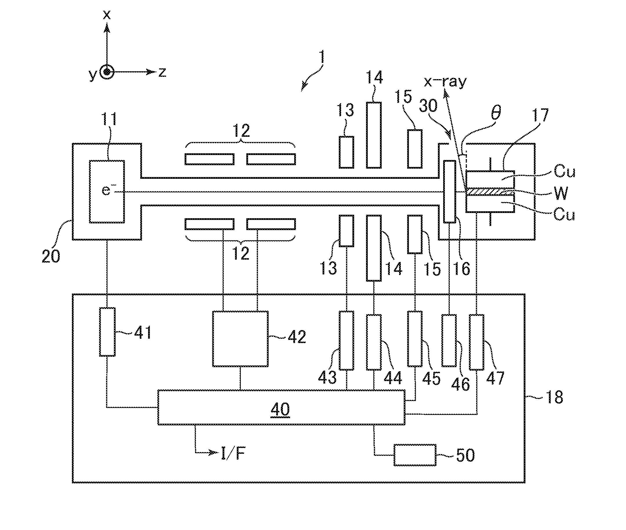
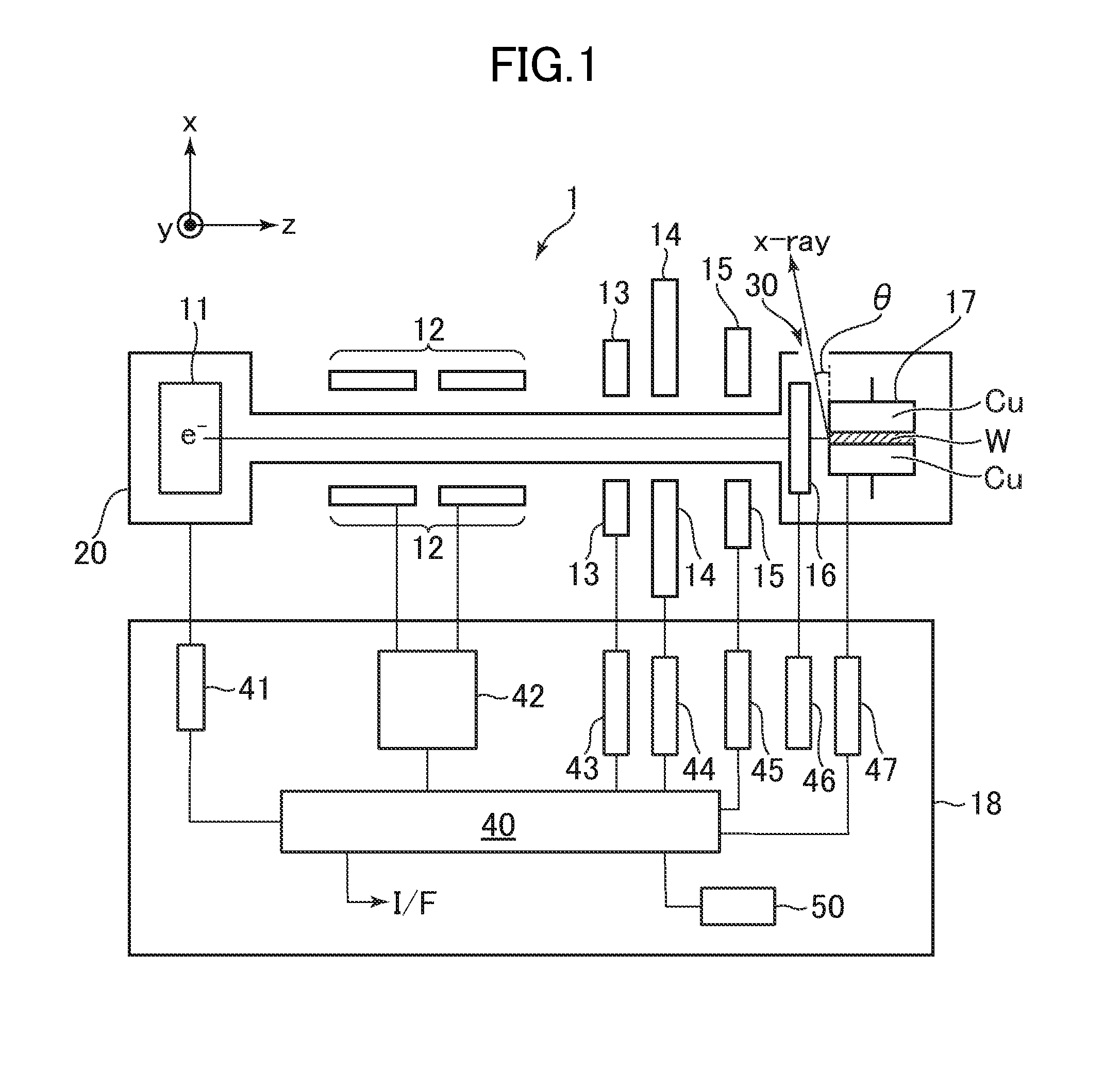
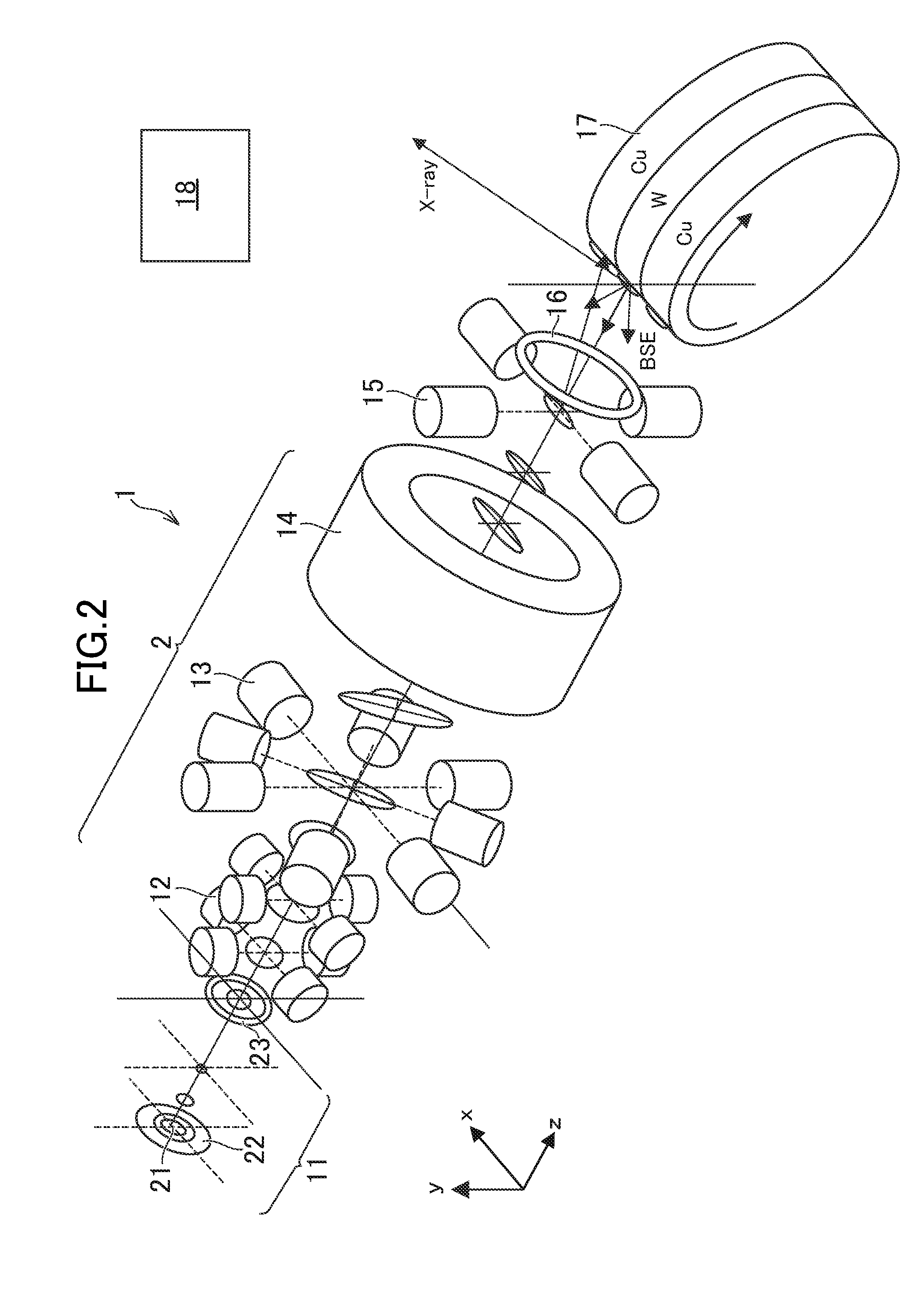
[0031]FIG. 1 and FIG. 2 are schematic diagrams for illustrating the structure of an X-ray generator 1 according to the embodiment of the present invention. FIG. 1 is a block diagram of the X-ray generator 1, and FIG. 2 is a perspective view of main components of the X-ray generator 1 with which sectional shapes of an electron beam are illustrated together. In FIG. 1 and FIG. 2, xyz coordinates, which are defined b...


PUM


Abstract

Provided are an X-ray generator capable of easily measuring a beam size of an electron beam on an electron target, and an adjustment method therefor. The X-ray generator includes an electron target including a first metal, a second metal different from the first metal, and a third metal different from the second metal, which are sequentially arranged side by side along a first direction in a continuous manner.

Description

CROSS-REFERENCE TO RELATED APPLICATION[0001]The present application claims priority from Japanese application JP 2015-096316 filed on May 11, 2015, the content of which is hereby incorporated by reference into this application.BACKGROUND OF THE INVENTION[0002]1. Field of the Invention[0003]The present invention relates to an X-ray generator, and more particularly, to an X-ray generator having an electron-beam adjusting function and an adjustment method therefor.[0004]2. Description of the Related Art[0005]In general, in an X-ray generator, an X-ray is generated by causing an electron beam at a high speed to collide against an electron target. Hitherto, a focal spot size of the X-ray emitted from the X-ray generator is generally measured by mounting a screen or the like having a pinhole on an X-ray emitting side of the X-ray generator and photographing a magnified image with an X-ray CCD camera or the like (pinhole photography).SUMMARY OF THE INVENTION[0006]The X-ray generator is sol...

Claims


Application Information

Patent Timeline
Patent Type & Authority Applications(United States)
IPC IPC(8): H01J35/14H01J35/02H05G1/26H01J35/08
CPCH01J35/14H01J35/08H01J2235/081H05G1/26H01J2235/088H01J35/025H01J2235/086H05G1/02H01J35/147H01J35/153
Inventor NONOGUCHI, MASAHIRONOGUCHI, MANABUKATO, KOICHINISHIDA, RYUJIKUSAKA, YUJIKAGEYAMA, MASASHICHAKI, TOMOHIRO
Owner RIGAKU CORP
Learn More