Method and Apparatus of Latency Measurement for LTE-WLAN Aggregation

a technology of aggregation and latency measurement, applied in the field of wireless communication, can solve the problems of affecting the performance of core network approaches, requiring additional solutions, and requiring continuous rising data traffic, and achieves significant capacity and quality of experience improvement

Inactive Publication Date: 2016-11-17
HFI INNOVATION INC
View PDF6 Cites 43 Cited by
  • Summary
  • Abstract
  • Description
  • Claims
  • Application Information

AI Technical Summary

Benefits of technology

[0007]LWA (LTE / WLAN Aggregation) is a tight integration at radio level which allows for real-time channel and load aware radio resource management across WLAN and LTE to provide significant capacity and quality of experience (QoE) improvements. When enabling LWA, packets are routed to a base station (eNB) for performing PDCP functionalities as an LTE PDU. Afterwards, the eNB can schedule the PDU either translated over LTE link or WLAN link. The eNB can acquire packet delay information regarding the WLAN link or obtain PDCP layer performance feedback from the UE. As a result, the eNB can adjust PDCP parameter setting and LWA scheduling accordingly.

Problems solved by technology

However, the continuously rising demand for data traffic requires additional solutions.
The current approaches of interworking of LTE and WLAN suffer from various limitations that hamper the benefits of LTE-WLAN interworking.
However, the core network approaches suffer from significant performance shortcomings.
These approaches are unable to react to dynamically varying radio conditions and do not permit aggregation of IP flows over LTE and WLAN access.
While the RAN assisted IWK feature promises to improve Quality of Experience (QoE) and network utilization, it is also limited by the inability to aggregate IP flows as well as support of limited traffic granularity at the PDN level.
Unfortunately, such CP / UP interface does not exist under LWA and eNB fails to understand the backhaul delay information and WLAN's PDCP PDU delivery status when PDU is translating to WLAN link.
Moreover, deciding the traffic dispatching ratio only based on channel condition and AP loading, it is still difficult for eNB to estimate the overall packet delay when the PDU is translating to WLAN link and thus not able to provision the QoS requirement.

Method used


Image

  • Method and Apparatus of Latency Measurement for LTE-WLAN Aggregation
  • Method and Apparatus of Latency Measurement for LTE-WLAN Aggregation
  • Method and Apparatus of Latency Measurement for LTE-WLAN Aggregation

Examples


Embodiment Construction

[0024]Reference will now be made in detail to some embodiments of the invention, examples of which are illustrated in the accompanying drawings.

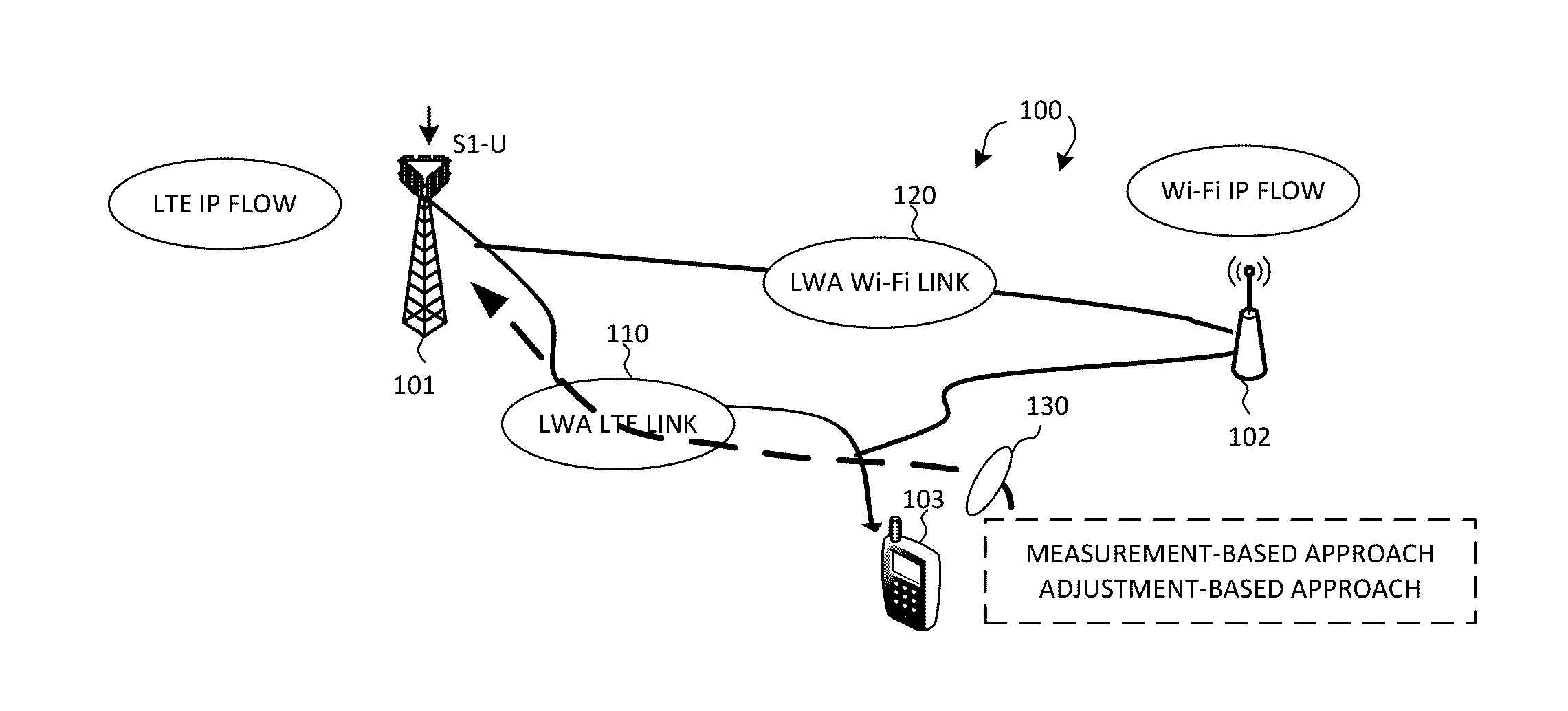
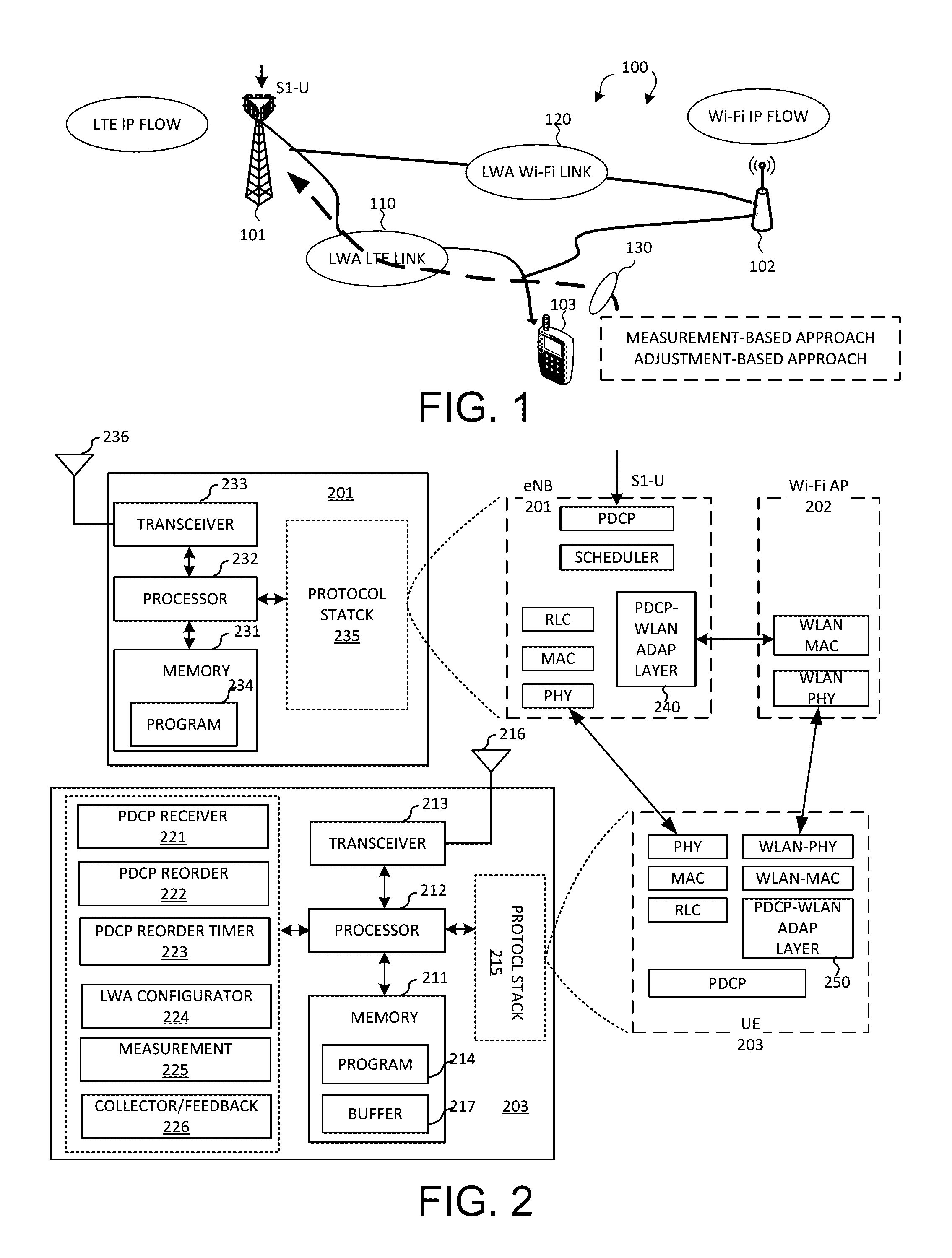
[0025]FIG. 1 illustrates a system diagram of a wireless network 100 with LTE-WLAN aggregation (LWA) in accordance with embodiments of the current invention. Wireless network 100 comprises a base station eNB 101 that provides LTE cellular radio access via E-UTRAN, an access point AP 102 that provides Wi-Fi radio access via WLAN, and a user equipment UE 103. LTE-WLAN Aggregation (LWA) is a tight integration at radio level, which allows for real-time channel and load-aware radio resource management across LTE and WLAN to provide significant capacity and Quality of Experience (QoE) improvements. When enabling LWA, S1-U interface is terminated at eNB 101 whereby all IP packets are routed to eNB 101 and performed with PDCP layer operations as an LTE PDU. Afterwards, eNB 101 can schedule whether LWA-LTE link 110 or LWA-Wi-Fi link 120 the LTE PDU sh...


PUM


Abstract

LWA (LTE-WLAN Aggregation) is a tight integration at radio level which allows for real-time channel and load aware radio resource management across WLAN and LTE to provide significant capacity and quality of experience (QoE) improvements. When enabling LWA, packets are routed to a base station (eNB) for performing PDCP functionalities as an LTE PDU. Afterwards, the eNB can schedule the PDU either translated over LTE link or WLAN link. The eNB can acquire packet delay information regarding the WLAN link or obtain PDCP layer performance feedback from the UE. As a result, the eNB can adjust PDCP parameter setting and LWA scheduling accordingly.

Description

CROSS REFERENCE TO RELATED APPLICATIONS[0001]This application claims priority under 35 U.S.C. §119 from U.S. Provisional Application No. 62 / 162,265 entitled “Method and Apparatus of Latency Measurement for LTE-WLAN Aggregation” filed on May 15, 2015, the subject matter of which is incorporated herein by reference.TECHNICAL FIELD[0002]The disclosed embodiments relate generally to wireless communication, and, more particularly, to latency measurement and reporting for LTE-WLAN aggregation.BACKGROUND[0003]Mobile data usage has been increasing at an exponential rate in recent year. A Long-Term Evolution (LTE) system offers high peak data rates, low latency, improved system capacity, and low operating cost resulting from simplified network architecture. In LTE systems, an evolved universal terrestrial radio access network (E-UTRAN) includes a plurality of base stations, such as evolved Node-B's (eNBs) communicating with a plurality of mobile stations referred as user equipment (UEs). How...

Claims


Application Information

Patent Timeline
Patent Type & Authority Applications(United States)
IPC IPC(8): H04W72/08H04W76/04
CPCH04W76/046H04W72/085H04W28/12H04W84/042H04W84/12H04W76/15H04W28/0236H04W88/06H04W76/27
Inventor CHOU, CHIE-MINGHSU, CHIA-CHUNNUGGEHALLI, PAVAN SANTHANA KRISHNA
Owner HFI INNOVATION INC
Why Eureka
Try Eureka