Cavitation Device

a cavitation device and cavitation tube technology, applied in the direction of liquid fuel engines, machines/engines, transportation and packaging, etc., can solve the problems of heat energy to be imparted into the liquid, impeller blades, and damage to the pump, so as to facilitate the pumping effect and ameliorate the drag

Active Publication Date: 2016-11-24
HIGHLAND FLUID TECH
View PDF3 Cites 5 Cited by
  • Summary
  • Abstract
  • Description
  • Claims
  • Application Information

AI Technical Summary

Benefits of technology

[0013]By the incorporation of at least one rotating disc having an open center for the passage of liquid, and with an appropriate housing design for intake and outflow, we are able to use the same motor that turns the cavitation device rotor to turn the disc also, thus utilizing the disc in combination with the cavitation rotor as a kind of disc pump to pass the liquid through the cavitation device. The rotating disc not only facilitates a pumping effect, but ameliorates the counterproductive drag imposed by the stationary housing wall of the unit.
[0014]In this continuation-in-part, the function and benefits of the central, or coaxial, inlet which facilitates the flow path through the open center of the disc have been further developed. This continuation-in-part utilizes a tapered flow director aligned with the rotating shaft and facing the central (coaxial) inlet to enhance the heating, mixing, and pumping effects of the device. The flow director is an improvement on the accelerator seen in FIG. 6. FIGS. 8-12 relate to the utilization of a flow director immediately next to the coaxial inlet guiding the fluid to distribution over the cavitation surface of the rotor; In FIG. 13, the flow director receives the incoming fluid through a rotating disc.
[0015]Our combined disc pump and cavitation device is inherently safer than the conventional use of a positive displacement pump to force the mixture through a separate cavitation device, in that, if there is a blockage of some sort, excess pressure will not build up within the device. Although the disc, or discs, will continue turning, they will generate only a relatively low pressure within the device.

Problems solved by technology

The phenomenon of cavitation, as it sometimes happens in pumps, is generally undesirable, as it can cause choking of the pump and sometimes considerable damage not only to the pump but also auxiliary equipment.
The phenomenon of cavitation in all previous devices relevant hereto is caused by the rapid passage of the liquid over the cavities, which creates a vacuum in them, tending to vaporize the liquid; the vacuum is immediately filled again by the liquid and created again by the movement of the liquid, causing extreme turbulence in the cavities, further causing heat energy to be imparted into the liquid.
Centrifugal pumps tend also to break large particles such as drill cuttings into small, low gravity particles which are more difficult to separate by centrifugation.
The impeller blades of many types of pumps will fracture and break solids into smaller particles which may resist separation by any conventional method.
Cavitation devices are excellent for intimately mixing gases with liquids, but centrifugal pumps do not handle large volumes of gases well, sometimes losing the ability to pump at all when the gas volume is too great.
Moreover, in the conventional cavitation devices, there is a viscous or surface effect drag against the stationary end wall of the cavitation device housing.
Rotating cavitation devices in the past generally have not been designed to optimize the flow of the incoming fluid, which must find its way from an inlet on one side of the rotor to and through the cavitation zone between the cylindrical interior of the housing wall and the cavities on the periphery of the rotor.
Workers in cavitation mixing and heating in the past have generally not attempted to analyze and improve the flow patterns of the treated material on either the incoming or outgoing sides of the rotor, to achieve greater uniformity of heating and mixing.

Method used


Image

  • Cavitation Device
  • Cavitation Device
  • Cavitation Device

Examples


Embodiment Construction

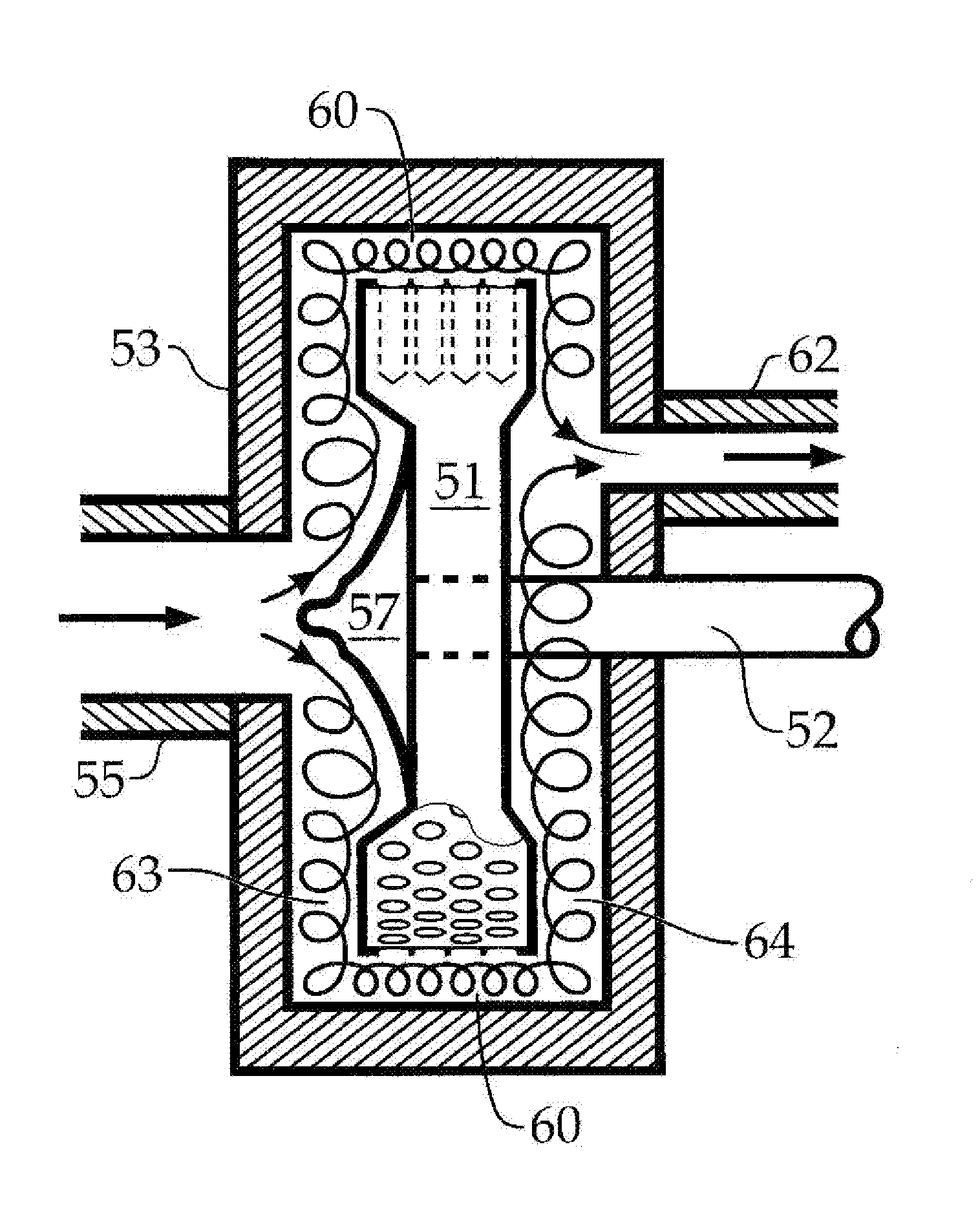
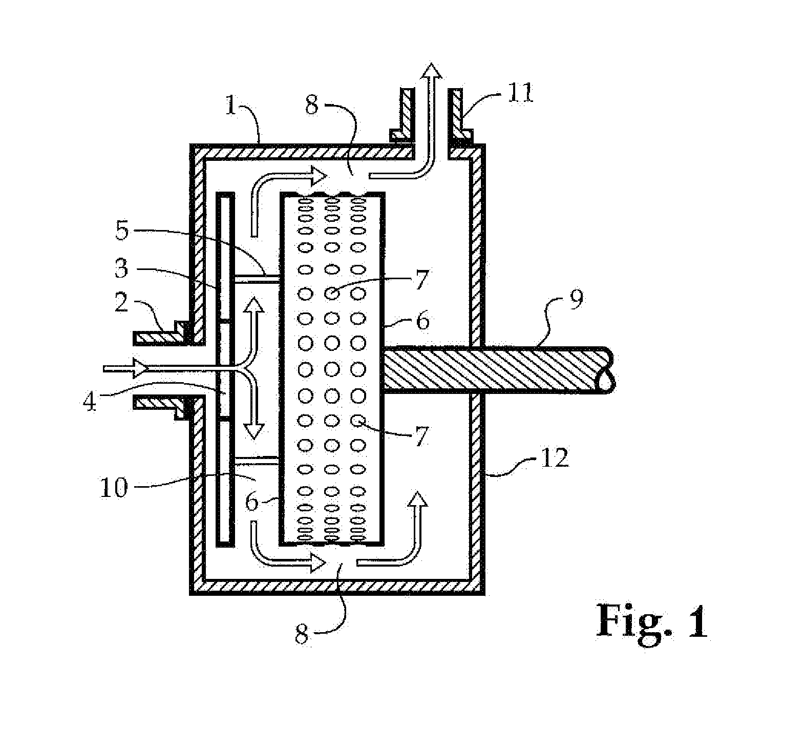
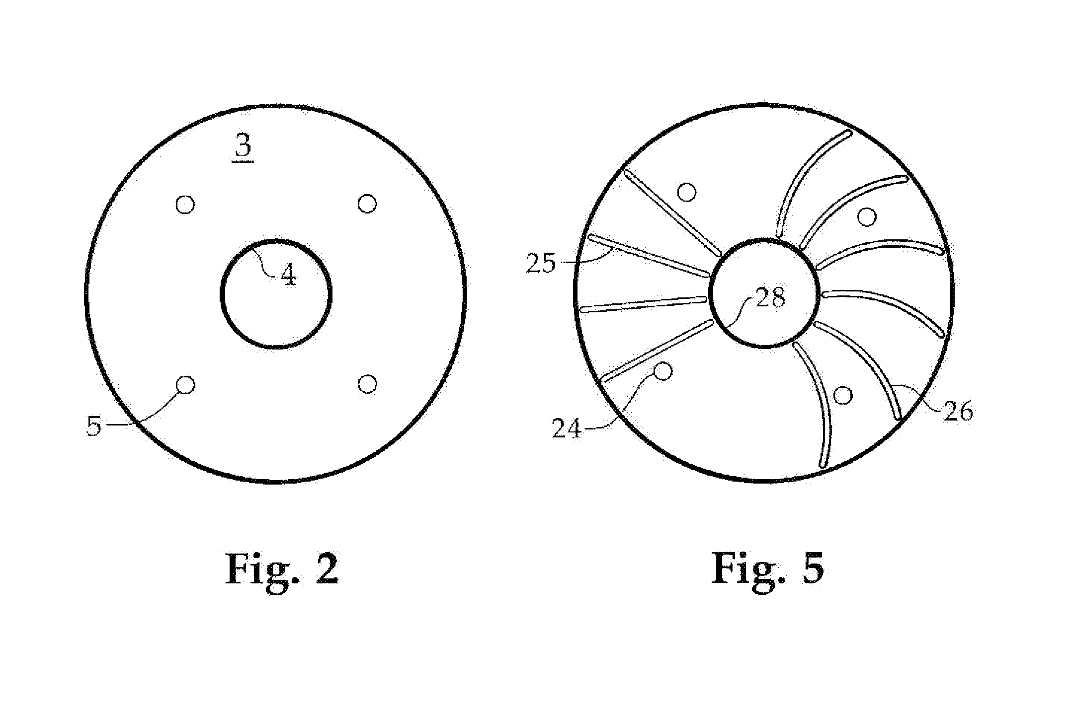
[0031]Referring first to FIG. 1, the cavitation pump is shown in section and more or less diagrammatically. Fluid enters a housing 1 through a conduit 2 passing through central hole 4 in solid disc 3. Solid disc 3 is held in place by disc supports 5, which are attached to cavitation rotor 6. Cavitation rotor 6 is substantially cylindrical in shape and has a plurality of cavities 7 on its cylindrical surface. Housing 1 is also substantially cylindrical in shape so that its inside surface can accommodate the cylindrical surface of the cavitation rotor 6 substantially concentrically and in close proximity. That is, the peripheral space 8 between the cavitation rotor 6 and the substantially concentric internal surface of the housing 1 is somewhat constricted to enhance the efficiency of the cavitation effects on the fluid, as will be explained more fully below. Cavitation rotor 6 is mounted on a shaft 9 which passes through the end wall 12 of housing 1 by way of a thrust bearing having ...


PUM


Abstract

An improved cavitation mixing and heating device employs an inlet directed toward the vertex of a conical or similar flow-directing element. The flow patterns of the fluid material to be mixed and heated are designed to preheat, spread, and create turbulent flow mixing of the fluid before it enters the cavitation zone, using heat generated in the cavitation zone that is conducted through the body of the cavitation rotor. The functions of the axially oriented inlet and flow directing element are assisted by a cantilever construction to alleviate stress on the bearings.

Description

CROSS REFERENCE TO RELATED APPLICATION[0001]0001 This application is a Continuation-in-Part of U.S. patent application Ser. No. 14 / 715,160 filed May 18, 2015 which claims the benefit of U.S. Provisional Application No. 62 / 200,116 filed on May 19, 2014, which are incorporated herein by reference in its entirety. This application also claims the benefit of U.S. Provisional Application No. 62 / 197,862 filed Jul. 28, 2015, which is also incorporated herein by reference in its entirety.TECHNICAL FIELD[0002]An axially-oriented inlet feeds fluid directly to the vertex of a generally conical, curved profile, or campanulate flow-directing face of a rotor containing cavities on its cylindrical surface. The flow director spreads the fluid to a cavitation zone formed between the cavity-containing surface and the closely conforming interior surface of a housing. The device pumps, heats and mixes the fluid. The device may contain discs to contribute an enhanced disc pump effect. The flow patterns ...

Claims


Application Information

Patent Timeline
Patent Type & Authority Applications(United States)
IPC IPC(8): B01F5/12B01F3/04F04D29/40F04D29/02F04D3/02F04D29/18B01F25/60
CPCB01F5/12F04D3/02F04D29/18B01F2215/0081F04D29/026B01F3/04985F04D29/406B01F27/1155B01F27/192B01F27/2722B01F27/73B01F27/93
Inventor SMITH, KEVIN W.FAIR, JEFF
Owner HIGHLAND FLUID TECH
Why Eureka
Try Eureka