

Networked control of a modular multi-level converter
a multi-level converter and converter technology, applied in adaptive control, power conversion systems, instruments, etc., can solve the problems of increasing the complexity of control requirements, increasing the weight, and the space necessary to accommodate the converter boards, and limiting the computational capability of the controller, so as to save wiring and/or galvanic isolation
- Summary
- Abstract
- Description
- Claims
- Application Information
AI Technical Summary
Benefits of technology
Problems solved by technology
Method used
Image

Examples
Embodiment Construction
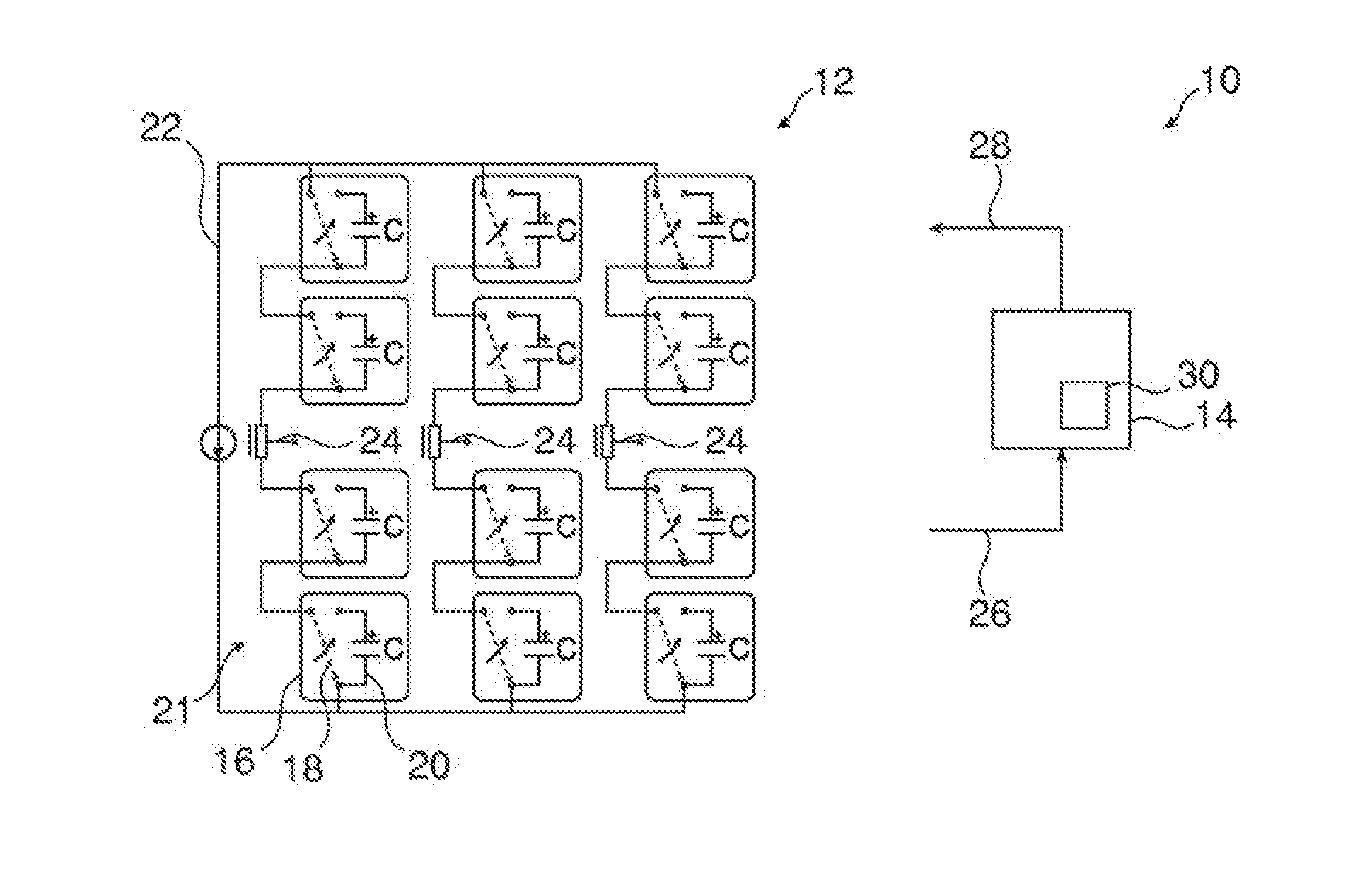
[0010]Model predictive control offers a series of benefits in controlling a modular topology. However, the computational load still may limit the applicability of such a technology. One strategy to overcome the limitations of a controller that is located physically with the system is to control the converter remotely. Remote control systems, however, comprise new challenging sets of problems because instantaneous and perfect signals between controller and converter may not be achievable. The communication medium between the controller and the converter may introduce delays of time-varying and possibly random nature, packet losses and bandwidth limitations. All these may degrade the achievable control performance of the converter system and could even possibly destabilize the process.
[0011]It is an objective of the invention to provide a more flexible and more accurate model predictive control schema for a modular multi-level converter under unreliable communication.
[0012]This object...
PUM
 Abstract
Description
Claims
Application Information