Method and apparatus for detecting the position and the orientation of an interventional device

a technology of positioning and positioning, applied in the direction of magnetic variable regulation, diagnostics, sensors, etc., can solve the problems of affecting the operation etc., to achieve the effect of reducing the time for getting mr images and reducing the information about the position and orientation of the interventional devi

Inactive Publication Date: 2007-07-03
DEUTES KREBSFORSCHUNGSZENT STIFTUNG DES OFFENTLICHEN RECHTS
View PDF17 Cites 14 Cited by
  • Summary
  • Abstract
  • Description
  • Claims
  • Application Information

AI Technical Summary

Benefits of technology

[0027]One advantage of the present invention according to at least one embodiment is that no visual contact with the Faraday sensor is necessary. Furthermore, localizing the sensor is not dependent upon MR imaging and the corresponding image formation, since it is carried out only by determining the local magnetic field at the position of the sensor with the help of field gradients.
[0028]In a preferred embodiment of the present invention, the Faraday sensor is a reflection type sensor. In this kind of sensor, the light passes through the active material (e.g. the crystal) of the Faraday sensor, is reflected and passes through the active material again in the other direction. The direction of rotation of the plane of polarization is the same for both paths of the light. Therefore, if the same beam of light is reflected back and forth through the active medium, the rotation of its plane of polarization is increased each time. The reflection of the light beam can either take place at a mirror behind the active medium of the Faraday sensor or at the end surface of the active medium itself. The reflection type sensor is advantageous because of its possible miniaturization, allowing the Faraday sensor to be integrated easily into very small interventional devices.
[0029]The magnetic resonance imaging apparatus provides the magnetic fields for MR imaging and for the method according to the invention. The magnetic fields applied for MR imaging, particularly the field gradients, are usually very complex. The magnetic fields used for determining the position and the orientation of an interventional device can be chosen much simpler, in order to keep the evaluation of the measured data (in step C)) fairly simple.
[0030]In the preferred embodiment of the present invention, the magnetic fields provided by the magnetic resonance imaging apparatus are used for both the MR imaging and the measurement of the position and the orientation of the interventional device. By using the same magnetic fields for both purposes, the time for getting MR images and the information about the position and orientation of the interventional device is reduced. Long scan times limit the applicability of MR-imaging techniques to the general patient population. In particular, long scan times lead to artifacts in the MR images due to involuntary patient movements and motion of the interventional device. Therefore the scan time should be reduced as much as possible.
[0031]In the preferred embodiment of the present invention, an image of the interventional device is superimposed upon independently acquired diagnostic images at the position as determined in step C) of the method according to the invention. The position of the interventional device (and possibly its orientation) is displayed on a display device (e.g., a computer monitor) by superposition of a graphic symbol on a conventional MR image. In alternative embodiments of the invention, a graphic symbol representing the interventional device is superimposed on diagnostic images obtained with other imaging systems such as a computer tomography (CT) scanner, an ultrasound scanner or a positron emission tomography (PET) system. Other embodiments of the invention display the position and the orientation of the interventional device numerically or as a graphic symbol without reference to a medical diagnostic image.
[0032]Preferably the interventional device, the position and orientation of which are measured according to the present invention, is a guide wire, a catheter, an endoscope, a laparoscope, a biopsy needle, a surgical implement, a therapy delivery implement, an intravascular catheter, a radiofrequency ablation device, a cryo-cooling device or a similar device.

Problems solved by technology

Furthermore, if the contrast between the device and its surroundings is too low, it cannot be detected.
However, compounds and materials considered MR-compatible, and even MR contrast agents, can produce significant distortion artifacts that obscure the anatomy and physiology of the imaged tissue.
If the device is connected to an electrical conductor with one or more windings and if these windings are passed by a direct current, a local distortion of the magnetic field of the MR-imaging apparatus is caused.
This distortion causes a local alteration of the MR image.
Within the magnetic radio frequency field of the MR-imaging apparatus, electric coupling of the wires, which are used as a current supply for the electrical conductor, can lead to severe heating under certain circumstances.
If the heat is not dissipated, it might result in a malfunction or even in the destruction of the device, which could be hazardous to the patient.
Therefore, the antenna is not compatible to all MR imagers.
Furthermore, dangerous RF-heating can take place which can be detrimental to the patient, and the MR technique has to be adapted to this kind of device tracking.
However, the presence of conductive elements in the catheter also introduces increased electronic noise and the possibility of Ohmic heating, and these factors have the overall effect of degrading the quality of the MR image and raising concerns about the patient's safety.
Unfortunately, the field of view is very limited when the interventional device is inside a patient's body and when the MR-imaging apparatus is closed.

Method used


Image

  • Method and apparatus for detecting the position and the orientation of an interventional device
  • Method and apparatus for detecting the position and the orientation of an interventional device
  • Method and apparatus for detecting the position and the orientation of an interventional device

Examples


example 1

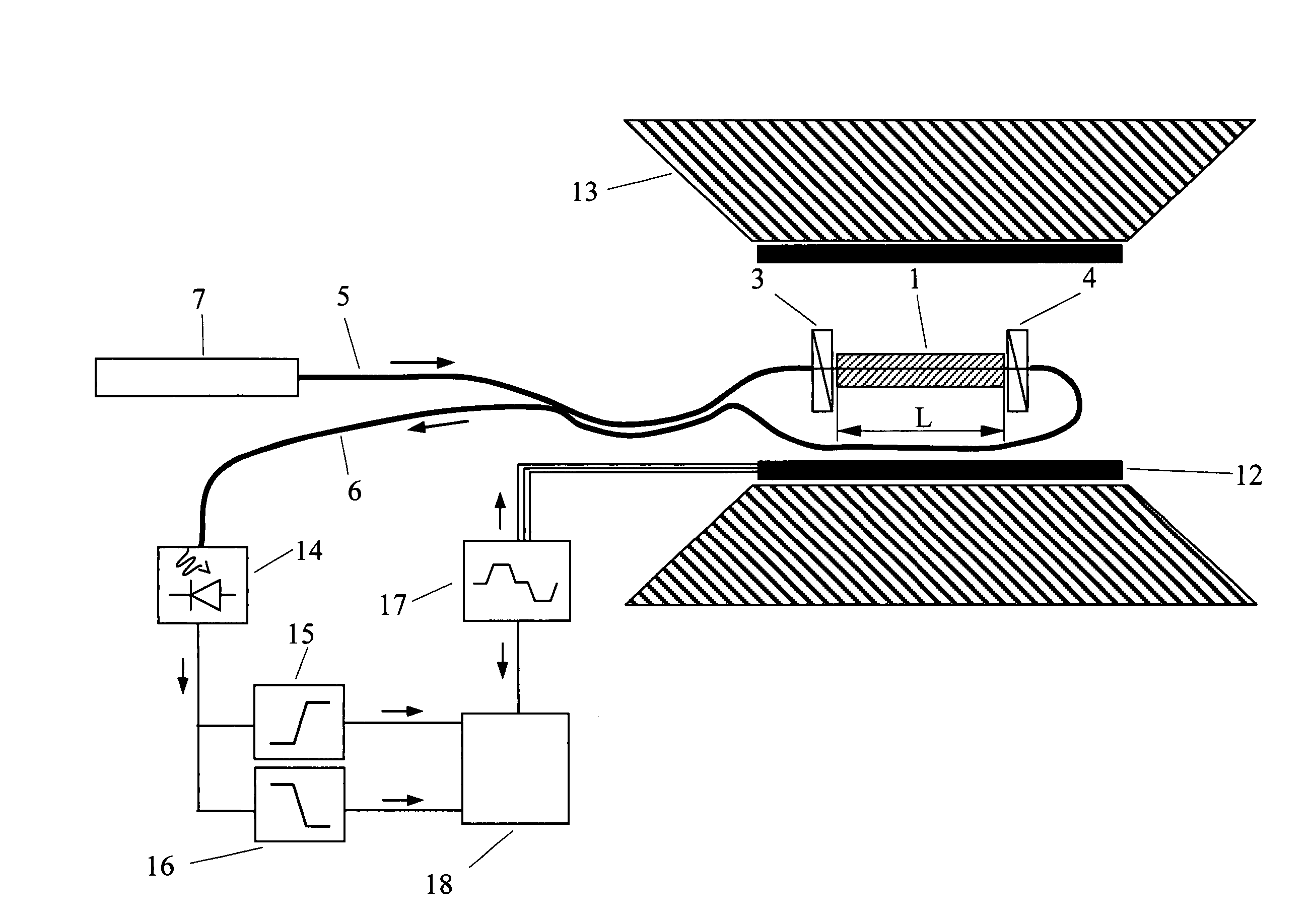
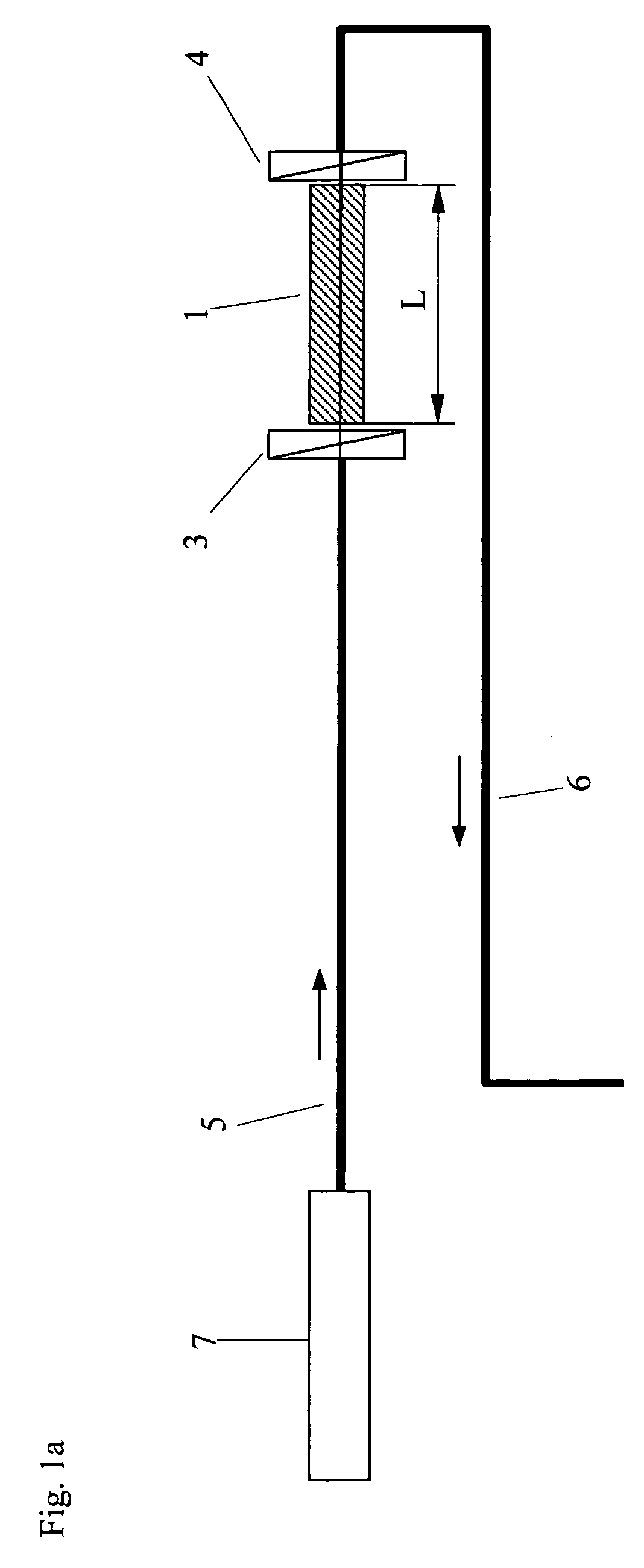
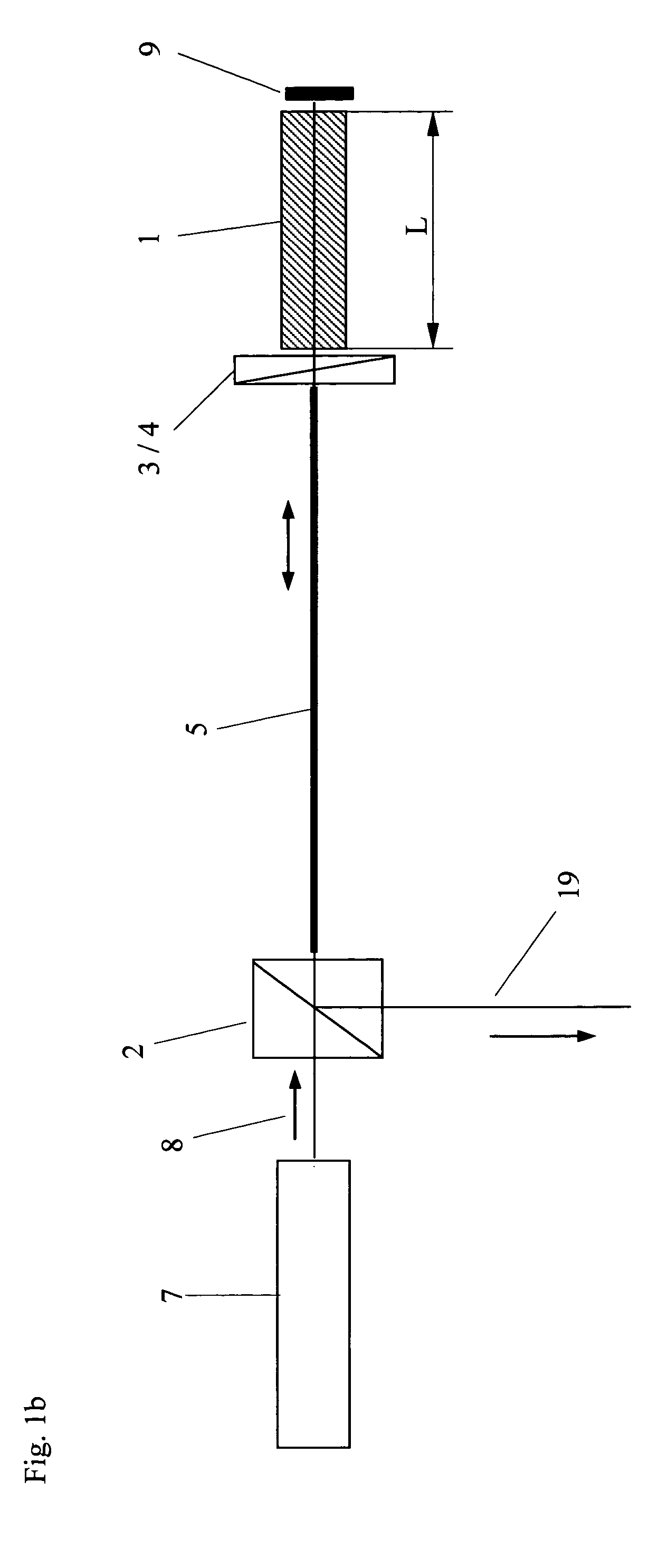
[0059]As the magneto-optically active material for the position sensor, a 7.5 mm-long crystal of Terbium-Gallium-garnet (TGG) was chosen, which offers a high Verdet constant of about 7 deg / T / mm at λ=675 nm. A diode laser (corresponding to model number DLS15, manufactured by Linos, Germany, in this experiment) was used as a light source and the light was coupled into the crystal through an optical fiber (core diameter: 63 μm) and a polarizing foil. A rotatable analyzer was placed directly behind the crystal and the power of the transmitted light was measured far away from the sensor using again an optical fiber for light transmission and a photo detector (transmission type sensor). Several different experiments were carried out: (a) The sensor was placed at the patient table of a commercial whole body 1.5 T MR scanner (corresponding to Siemens Magnetom Symphony in this experiment) and the Faraday rotation was measured with the sensor as a function of z-position and compared to the ma...


PUM


Abstract

The invention relates to a method and an apparatus for measuring the position and the orientation of an interventional device within a magnetic resonance imaging apparatus, the magnetic resonance image apparatus providing a static magnetic field B0 and magnetic field gradients with known magnetic flux densities and directions. The invention includes attaching a Faraday sensor to the interventional device, the Faraday sensor being connected to an optical measuring device. The method also includes using the optical measuring device for measuring the rotation of the plane of polarization of linearly polarized light in the Faraday sensor, while exposing the interventional device: (i) to the static magnetic field B0, and (ii) to the field gradients in all three directions of space in addition to the static magnetic field B0. The method also includes determining the position and the orientation of the interventional device by evaluating the measured rotation of the plane of polarization of the linearly polarized light.

Description

BACKGROUND OF THE INVENTION[0001]A. Field of the Invention[0002]The present invention relates to a method and an apparatus for detecting the position and the orientation of an interventional device, using a Faraday sensor.[0003]B. Description of the Related Art[0004]Modern interventional and surgical procedures aim to treat the affected tissue by causing minimal injury to healthy tissue structures. Special instruments (e.g., a catheter, an endoscope, or a laparoscope) are delivered to the target region via a small-sized (minimal) surgical opening and the affected tissue is treated.[0005]The target of the minimally invasive operation is often not directly visible for an interventionist (i.e., a surgeon), thus the operations are done under imaging guidance. X-ray fluoroscopy, computed tomography, ultrasound and optical endoscopy are currently the most frequently used imaging methods. However, magnetic resonance imaging (MRI) is a state of the art imaging modality for medical diagnosti...

Claims


Application Information

Patent Timeline
Patent Type & Authority Patents(United States)
IPC IPC(8): G01B11/14G01R33/032G01R33/28
CPCG01R33/0322G01R33/287
Inventor BOCK, MICHAELUMATHUM, REINERZABEL, HANS-JOACHIM
Owner DEUTES KREBSFORSCHUNGSZENT STIFTUNG DES OFFENTLICHEN RECHTS
Why Eureka
Try Eureka