Compact electroacoustic transducer and loudspeaker system and method of use thereof

a technology of electroacoustic transducers and loudspeakers, applied in the field of loudspeakers, can solve the problems of affecting the sound quality of speakers,

Active Publication Date: 2016-11-24
BRANE AUDIO LLC
View PDF13 Cites 24 Cited by
  • Summary
  • Abstract
  • Description
  • Claims
  • Application Information

AI Technical Summary

Benefits of technology

[0023]FIG. 3 also shows an alternate vent configuration that has holes 3003 in the stators that allow air to flow to separate vent layers. The cross-sectional airflow area of the vents (through which the air flow is shown by arrows 3001) is much smaller than the pump membrane area (so that the air is compressed). FIG. 3 also shows how a simple housing 3004 can direct the desired sound 3005 toward the listener (up as shown in FIG. 3) and the undesired out of phase sound away from the listener (down as shown in FIG. 3). The desired sound 3005 is in the low sub-woofer range to mid-range (20 Hz to about 3000 Hz).

Problems solved by technology

These speakers are also bulky in part because large enclosures are used to muffle the sound radiating from the backside of the cone (which is out of phase with the front-facing audio waves).
Cone speakers also depend on mechanical resonance; a large “woofer” speaker does not efficiently produce high frequency sounds, and a small “tweeter” speaker does not efficiently produce low frequency sounds.
However, TA speakers are terribly inefficient, converting well under 1% of their electrical input into audio waves.
Otherwise, an audio system could produce pressure waves that are out of synch (due to the difference in distance between each pump and the speaker membrane) and thus these waves can partially cancel (lowering audio power) at certain pumping / audio frequencies.
This force also varies as the inverse square of the distance between the pump membrane and stator (and this characteristic can cause the audio output to be nonlinear / distorted with respect to the electrical input).
Thus, in practice, the amplitude of the membrane in pump / transducer is limited to less than half of its maximum travel (which lowers pumping speed and audio power).

Method used


Image

  • Compact electroacoustic transducer and loudspeaker system and method of use thereof
  • Compact electroacoustic transducer and loudspeaker system and method of use thereof
  • Compact electroacoustic transducer and loudspeaker system and method of use thereof

Examples


Embodiment Construction

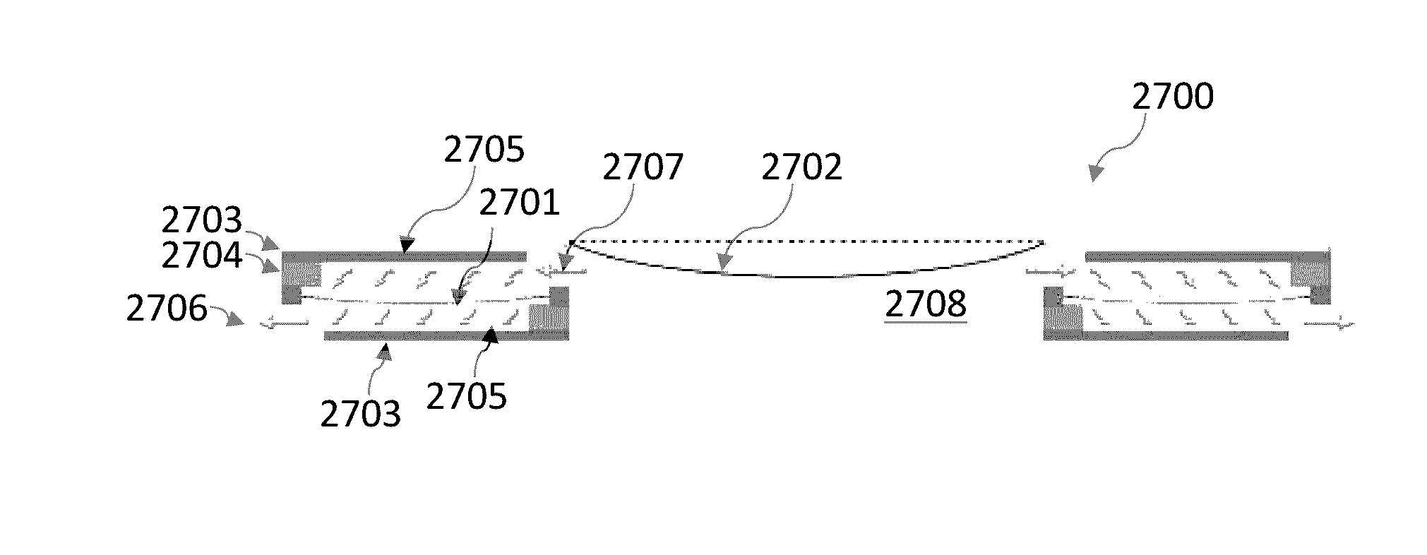
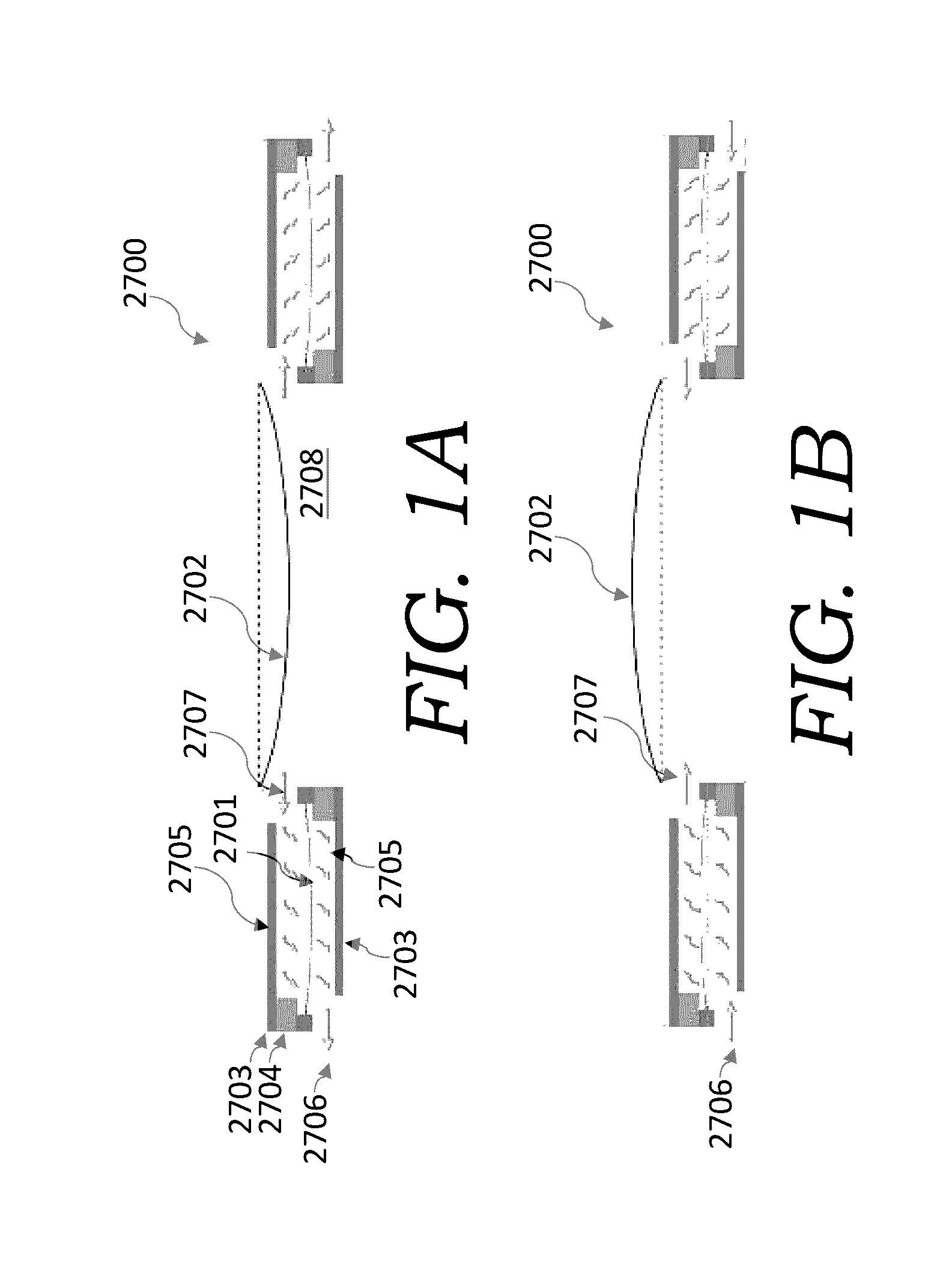
[0087]As set forth in the Pinkerton '615 application, it has been discovered that a loudspeaker having pump cards can generate good sound without the need for a rubber / PDMS membrane and that the use of a rubber / PDMS membrane can be avoided. It has further been discovered that using pump / driver cards to move air to / from the back of the device to the front (or front and side) of the device yields much less of a pressure drop than directing airflow toward a central chamber. By doing so, the pump cards are more efficient at low audio frequencies (20 Hz to 150 Hz) than higher frequencies (150 Hz to 20 kHz); accordingly, the embodiment of the present invention implements conventional electro-dynamic cone drivers above about 150 Hz. This was surprising as this exactly the opposite of what is taught in the art and sold commercially, which teaches that all electrostatic speakers using electro-dynamic cone drivers use them to handle low frequencies and electrostatic drivers to handle mid to h...


PUM


Abstract

An improved compact electroacoustic transducer and loudspeaker system. The electroacoustic transducer (or array of electroacoustic transducers) can generate the desired sound by the use of pressurized airflow. The electroacoustic transducer uses a shared stator with an array of vent support fingers and metal frame instead of two stators per electroacoustic transducer.

Description

RELATED PATENT APPLICATIONS[0001]This application is related to U.S. patent application Ser. No. 14 / 309,615, filed on Jun. 19, 2014 (the “Pinkerton '615 application”), which is a continuation-in-part to U.S. patent application Ser. No. 14 / 161,550, filed on Jan. 22, 2014. This application is also related to U.S. patent application Ser. No. 14 / 047,813, filed Oct. 7, 2013, which is a continuation-in-part of International Patent Application No. PCT / 2012 / 058247, filed Oct. 1, 2012, which designated the United States and claimed priority to provisional U.S. Patent Application Ser. No. 61 / 541,779, filed on Sep. 30, 2011. Each of these patent applications is entitled “Electrically Conductive Membrane Pump / Transducer And Methods To Make And Use Same.”[0002]This application is also related to U.S. Patent Application Ser. No. 62 / 113,235, entitled “Loudspeaker Having Electrically Conductive Membrane Transducers,” filed Feb. 6, 2015 (the “Pinkerton '235 application”).[0003]All of these above-ide...

Claims


Application Information

Patent Timeline
Patent Type & Authority Applications(United States)
IPC IPC(8): H04R1/02
CPCH04R1/02H04R1/26H04R1/2896H04R1/345H04R1/403H04R3/06H04R7/02H04R7/04H04R19/02H04R31/003H04R2307/023H04R2307/025H02M7/487H04R9/022H04R19/00H04R2201/003H04R19/01H04R19/013H04R19/005
Inventor PINKERTON, JOSEPH F.EVERETT, WILLIAM NEILLACKOWSKI, WILLIAM MARTINBADGER, DAVID A.
Owner BRANE AUDIO LLC
Why Eureka
Try Eureka