Base station, machine-to-machine (M2M) terminal, method, and computer readable medium

a technology of machine-to-machine terminal and base station, applied in the field of radio communication system, can solve the problems of reducing the maximum transmission rate of mtc ues, limiting the cost allowable for each m2m terminal, and reducing the cost. , to achieve the effect of improving the efficiency of determination

Active Publication Date: 2016-11-24
NEC CORP
View PDF4 Cites 29 Cited by
  • Summary
  • Abstract
  • Description
  • Claims
  • Application Information

AI Technical Summary

Benefits of technology

[0025]According to the above aspects, it is possible to provide a base station, an M2M terminal (MTC UE), a method, and a program contributing to improving efficiency of determination regarding whether to apply the ECM (i.e., the coverage enhancement processing in the ECM) to the MTC UE (M2M terminal). It should be noted that this effect is merely one of effects expected to be brought about by the embodiments disclosed in the specification.

Problems solved by technology

While M2M service providers need to distribute an enormous number of M2M terminals, there is a limit to the cost allowable for each M2M terminal.
Further, functional restrictions contributing to reduction of the cost include, for example, a low maximum transmission power, a small number of reception antennas, no support of high-order modulation schemes (e.g., 64 Quadrature Amplitude Modulation (64 QAM)), and a narrow operating bandwidth (e.g., 1.25 MHz), which lower the maximum transmission rate of MTC UEs.

Method used


Image

  • Base station, machine-to-machine (M2M) terminal, method, and computer readable medium
  • Base station, machine-to-machine (M2M) terminal, method, and computer readable medium
  • Base station, machine-to-machine (M2M) terminal, method, and computer readable medium

Examples


first embodiment

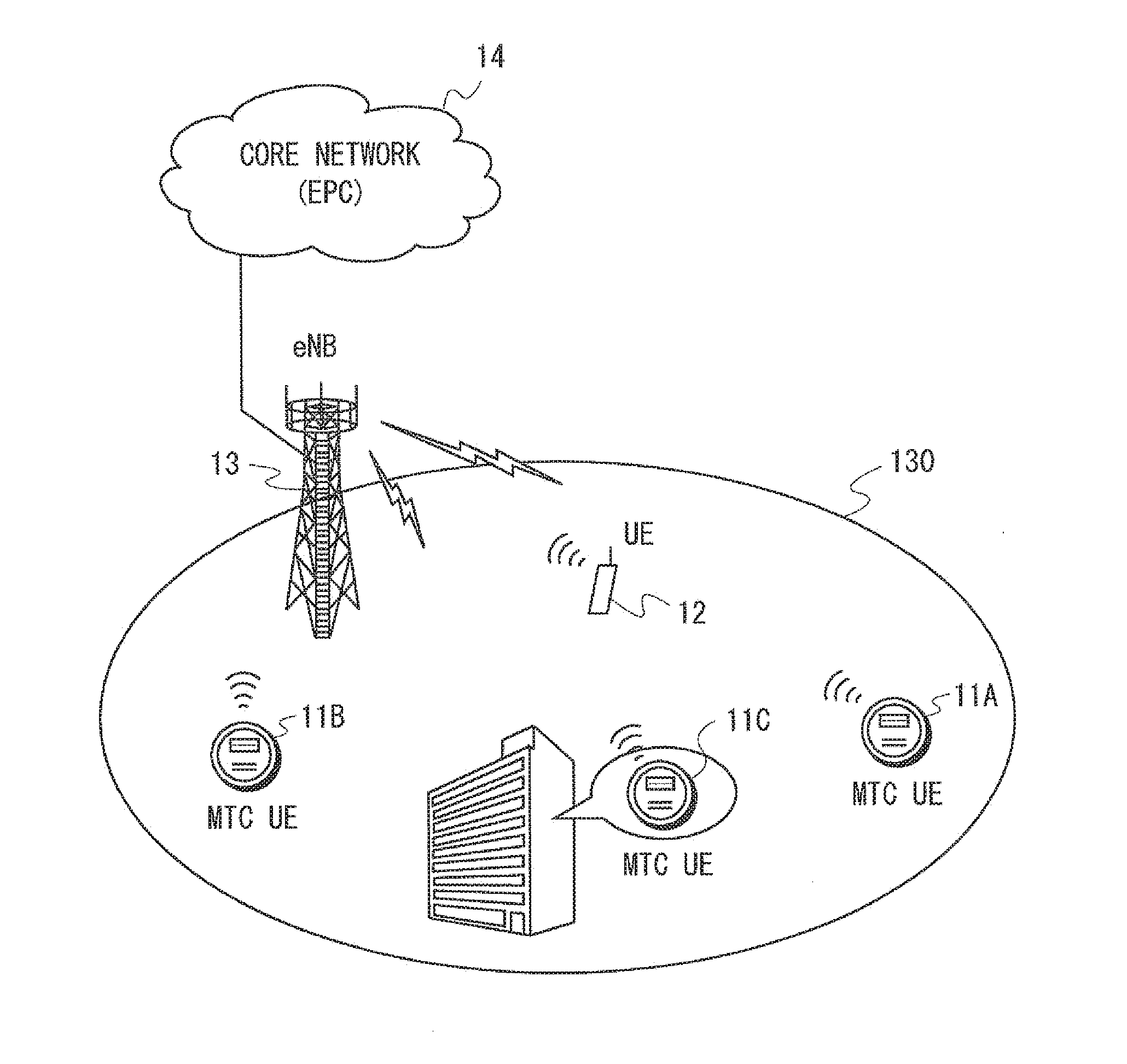
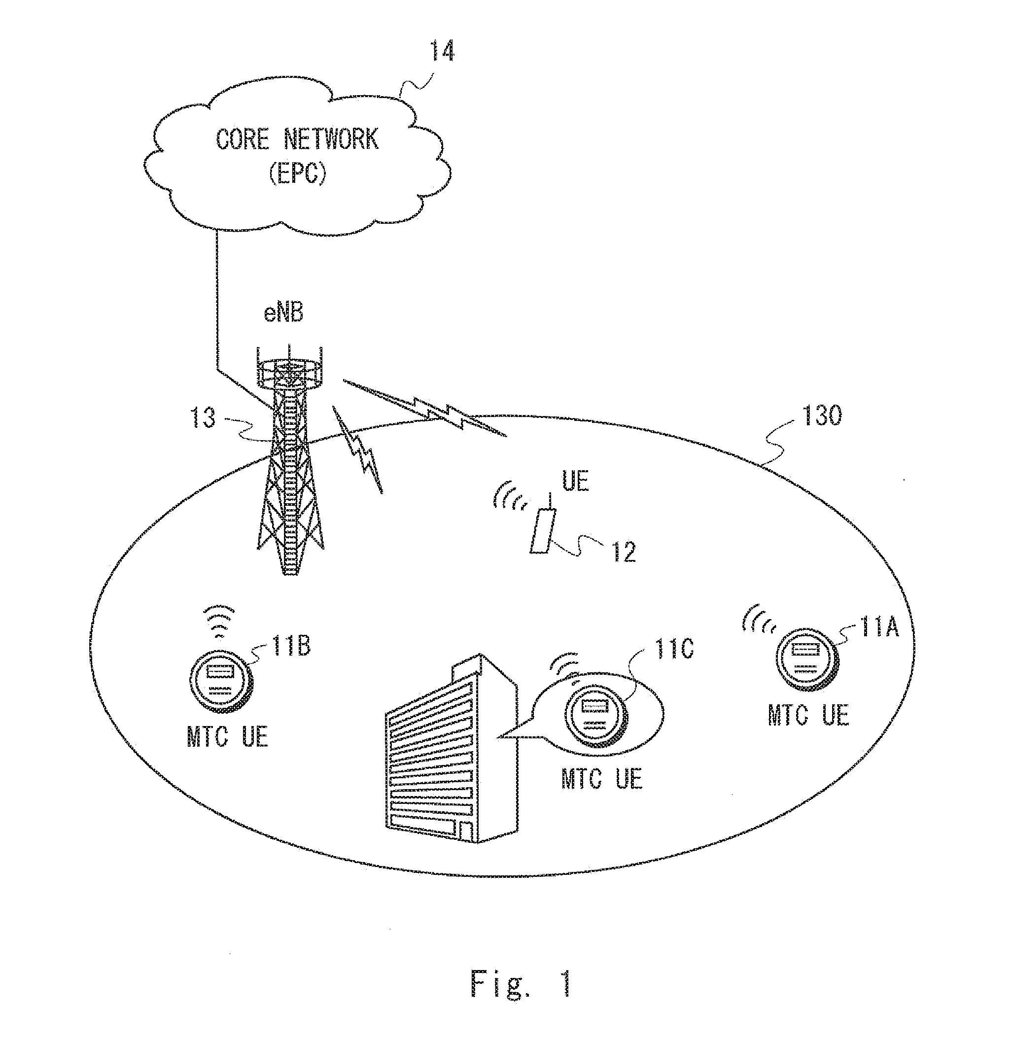
[0038]FIG. 1 shows a configuration example of a radio communication system according to this embodiment. This radio communication system provides communication services, such as voice communication or packet data communication or both, for example. With reference to FIG. 1, the radio communication system includes M2M terminals 11 (11A, 11B, 11C), a normal radio terminal 12 which is not an M2M terminal, a base station 13, and a core network 14. The radio terminal 12 is, for example, a mobile telephone, a smartphone, a tablet computer, or a notebook PC. The M2M terminals 11A, 11B, and 11C, and the radio terminal 12 are located in a cell 130 of the base station 13. In this embodiment, the radio communication system is described as being a 3GPP LTE system. That is, the M2M terminals 11 correspond to MTC UEs, the radio terminal 12 corresponds to a normal UE which is not an MTC UE, the base station 13 corresponds to an eNodeB (eNB), and the core network 14 corresponds to an Evolved Packet...

second embodiment

[0077]A configuration example of a radio communication system according to this embodiment may be the same as that of FIG. 1 described in the first embodiment. In the above first embodiment, the example in which the eNB 13 receives from the EPC 14 the history information indicating whether the coverage enhancement processing regarding the ECM (e.g., PDSCH / PUSCH repetition) was executed in previous communication with the MTC UE 11 has been shown. Alternatively, in this embodiment, an eNB 23 receives, from an MTC UE 21, history information indicating whether the coverage enhancement processing regarding the ECM (e.g., PDSCH / PUSCH repetition) was executed in previous communication of the MTC UE 21. The eNB 23 then controls communication between the MTC UE 21 and the eNB 23 using the coverage enhancement processing regarding the ECM based on the history information received from the MTC UE 21. For example, when the eNB 23 receives from the MTC UE 21 a notification indicating that the MT...

third embodiment

[0088]A configuration example of a radio communication system according to this embodiment may be the same as that of FIG. 1 described in the first embodiment. In this embodiment, a method for determining in an eNB 33 whether to apply the coverage enhancement processing regarding the ECM (e.g., PDSCH / PUSCH repetition) to a specific MTC UE 31 is described. The technical ideas described in this embodiment may be used alone or combination with the technical ideas described in the first or second embodiment stated above.

[0089]In this embodiment, the eNB 33 controls communication between the MTC UE 31 and the eNB 33 using the coverage enhancement processing regarding the ECM (e.g., PDSCH / PUSCH repetition) based on at least one of: a terminal capability of the MTC UE 31 (UE capability); terminal information on the MTC UE 31 (UE information); a communication characteristic of the MTC UE 31 (Communication performance); and radio quality of the MTC UE 31 (Radio quality), and further based on...


PUM


Abstract

A base station (13) is configured to receive, from a Machine-to-machine (M2M) terminal (11) or a core network (14), history information indicating whether or not specific coverage enhancement processing was executed in previous communication with the M2M terminal (11). Further, the base station (13) is configured to control communication using the specific coverage enhancement processing between the M2M terminal (11) and the base station (13) based on the history information received from the M2M terminal (11) or the core network (14). It is thus possible to contribute to improving efficiency of determination regarding whether to apply a special coverage enhancement processing to the M2M terminal.

Description

Technical Field[0001]The present disclosure relates to a radio communication system which performs a communication control in order to enhance coverage.BACKGROUND ART[0002]In the 3rd Generation Partnership Project (3GPP) Long Term Evolution (LTE), standardization of techniques for improving deterioration of communication quality due to recent sharp increase in mobile traffic and for achieving faster communication has been performed. Further, standardization of techniques for avoiding increase in a control signaling load due to connections of an enormous / number of Machine to Machine (M2M) terminals to an LTE network has been performed (Non-Patent Literature 1). The M2M terminals are, for example, terminals that perform communication without human intervention. The M2M terminals are placed in various types of equipment including machines (e.g., vending machines, gas meters, electric meters, vehicles, railway vehicles, and ships) and sensors (e.g., environmental, agricultural, and tra...

Claims


Application Information

Patent Timeline
Patent Type & Authority Applications(United States)
IPC IPC(8): H04W4/00H04W8/22H04W72/04H04W4/70
CPCH04W4/005H04W72/0413H04W8/22H04W72/0446H04W72/042H04W24/04H04W72/21H04W72/23H04W4/70Y02D30/70H04W92/045H04W16/26H04W68/005H04W92/10
Inventor FUTAKI, HISASHI
Owner NEC CORP
Why Eureka
Try Eureka