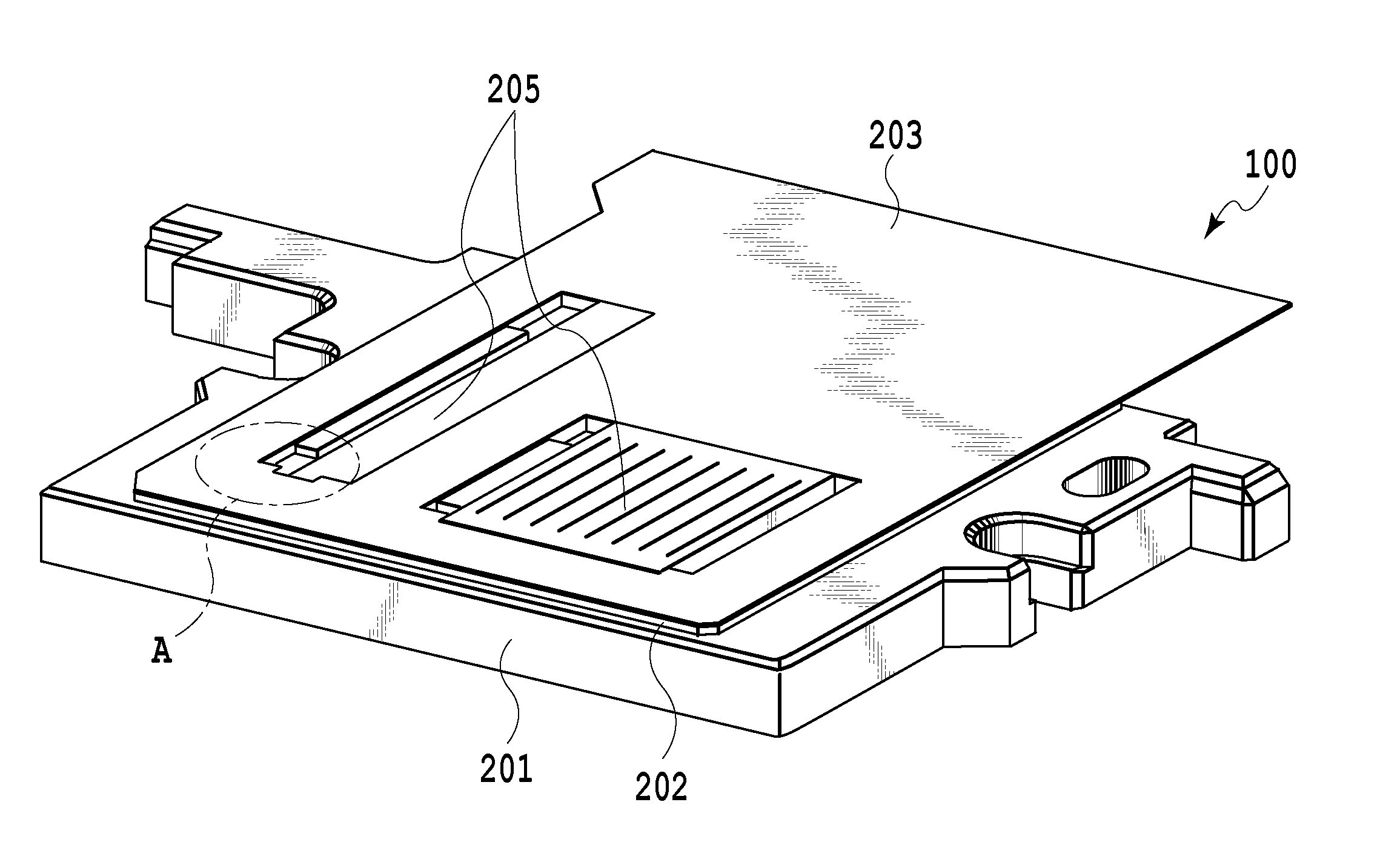
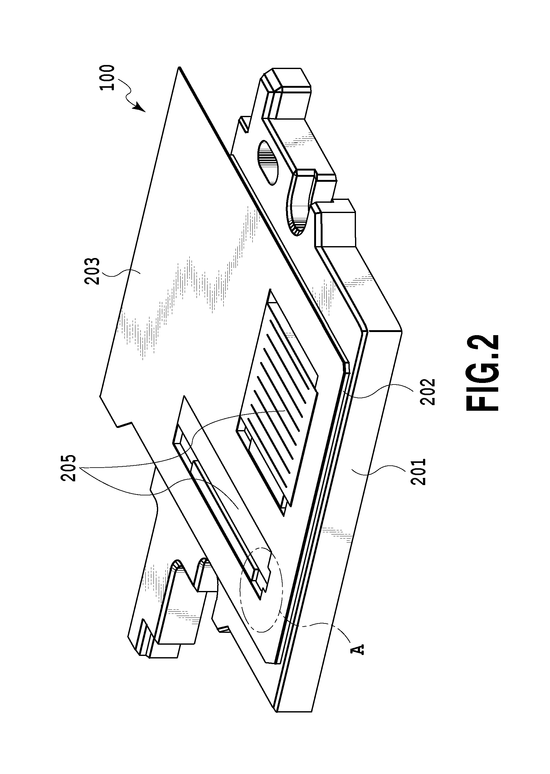
Liquid ejection head and liquid ejection apparatus
a technology of liquid ejection and liquid ejection, which is applied in the direction of printing, etc., can solve the problems of damage to the ejection element substrate, insufficient cleaning operation at the abraded portion, and inability to disclose a technique for sealing the second support member and the electrical wiring substra
- Summary
- Abstract
- Description
- Claims
- Application Information
AI Technical Summary
Benefits of technology
Problems solved by technology
Method used
Image
Examples
first embodiment
[0027]Hereinafter, a first embodiment of the present invention will be described with reference to the drawings.
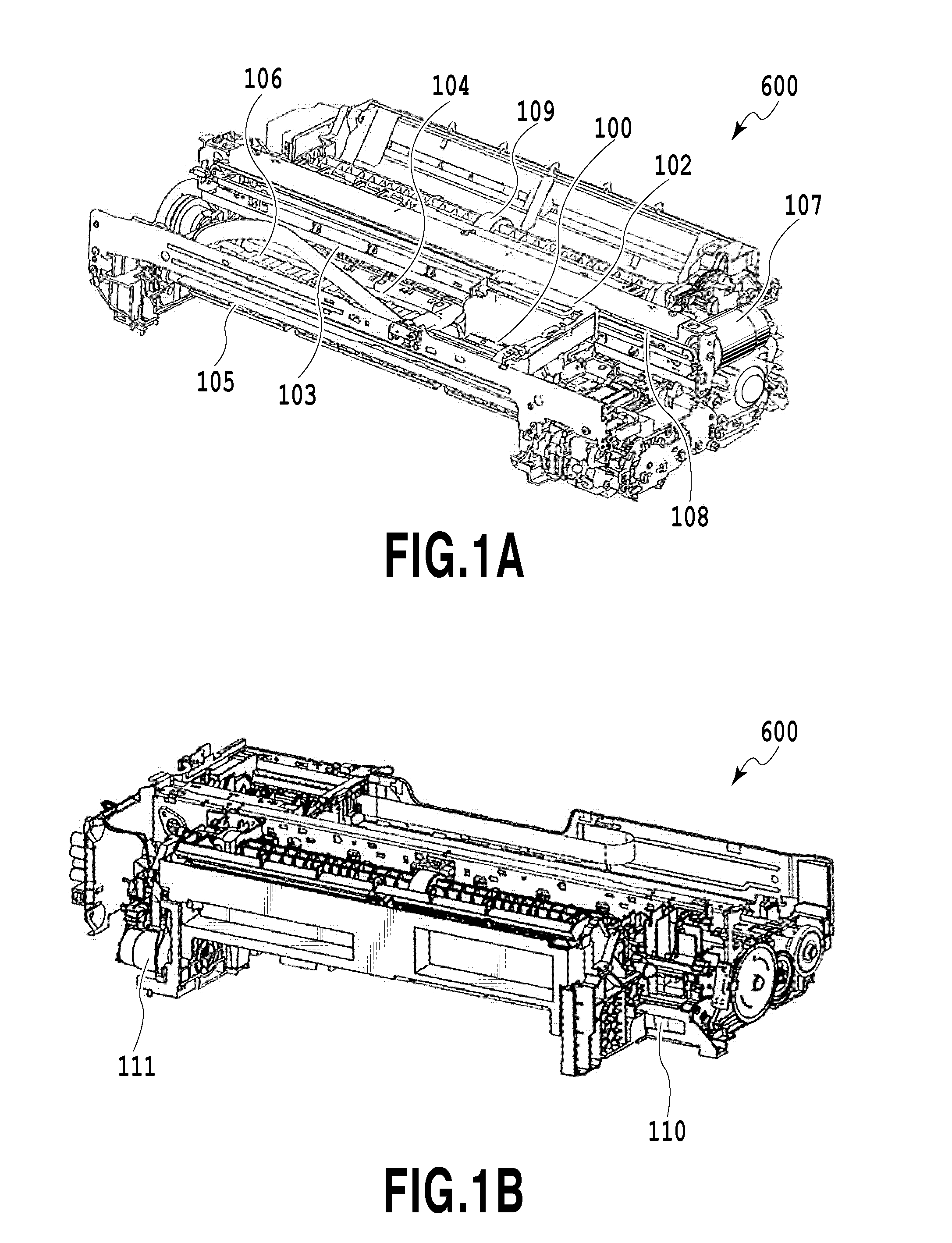
[0028]FIGS. 1A and 1B are perspective views illustrating a liquid ejection apparatus 600 according to the present embodiment. A carriage 102 equipped with a liquid ejection head 100 is supported so as to be movable in a reciprocating manner along a guide 103 extending in the main scan direction. The carriage 102 is driven by a carriage motor 107 through a belt 108.
[0029]A printing medium such as a sheet is fed by a sheet feeding roller 109 driven by a sheet feeding motor 111 of a sheet feeding mechanism through a gear set and is delivered onto a platen 106 by a conveying roller 104 and a pinching roller (not illustrated). A sheet discharging roller 105 is disposed at the downstream side of the platen 106 in the conveying direction and an auxiliary roller (not illustrated) comes into press-contact with the sheet discharging roller 105.
[0030]The conveying roller 104 and the ...
second embodiment
[0044]Hereinafter, a second embodiment of the present invention will be described with reference to the drawings. Furthermore, since the basic configuration of the present embodiment is similar to that of the first embodiment, only a characteristic configuration will be described below.
[0045]FIG. 6 is a cross-sectional view illustrating a part of a liquid ejection head 200 of the present embodiment and FIG. 7 is a partially enlarged perspective view of the liquid ejection head 200. A second support member 302 of the present embodiment includes a tapered surface 304 provided in the connection portion of a step portion 303. That is, a surface of the second support member 302 connecting the step surface 209 and the substrate mounting surface is formed as a tapered surface.
[0046]Since the tapered surface 304 is provided in this way, the sealant 206 can be caused to flow to a boundary surface between the electrical wiring substrate 203 and the second support member 302 by a capillary phe...
third embodiment
[0048]Hereinafter, a third embodiment of the present invention will be described with reference to the drawings. Furthermore, since the basic configuration of the present embodiment is similar to that of the first embodiment, only a characteristic configuration will be described below.
[0049]FIG. 8 is a cross-sectional view illustrating a part of a liquid ejection head 300 of the present embodiment and FIG. 9 is a partially enlarged perspective view of the liquid ejection head 300. A surface of a second support member 402 of the present embodiment connecting the step surface 209 of a step portion 403 to the substrate mounting surface is a curved surface 404. Since the curved surface 404 is provided in this way, the sealant 206 can be caused to flow to a boundary surface between the electrical wiring substrate 203 and the second support member 402 by a capillary phenomenon as indicated by the arrow of FIG. 9 even when the sealant having comparatively low viscosity is used. Accordingly...
PUM
 Abstract
Description
Claims
Application Information
 - R&D
- Intellectual Property
- Life Sciences
- Materials
- Tech Scout
- Unparalleled Data Quality
- Higher Quality Content
- 60% Fewer Hallucinations
Browse by: Latest US Patents, China's latest patents, Technical Efficacy Thesaurus, Application Domain, Technology Topic, Popular Technical Reports.
© 2025 PatSnap. All rights reserved.Legal|Privacy policy|Modern Slavery Act Transparency Statement|Sitemap|About US| Contact US: help@patsnap.com


