Swirler for a burner of a gas turbine engine

Inactive Publication Date: 2016-12-01
SIEMENS AG
View PDF7 Cites 0 Cited by
  • Summary
  • Abstract
  • Description
  • Claims
  • Application Information

AI Technical Summary

Benefits of technology

[0011]It is an object of the present invention to solve the aforesaid problems and drawbacks at least partly. In particular, it is an object of the present invention to provide fuel injection means, a swi

Problems solved by technology

Therefore, during part load operations of the gas turbine engine, poor mixing of fuel and air can occur.
The reliability of the gas turbine engine may be affected by such poor mixing of fuel and air.
In addition, due to poor mixing, a good portion of liquid fuel cannot atomize and therefore liquid ligaments often attach and/or are deposited to the internal surface of the components and form a carbon buildup.
When running the gas turbine engine at a part load or at a low load, the engine may

Method used


Image

  • Swirler for a burner of a gas turbine engine
  • Swirler for a burner of a gas turbine engine
  • Swirler for a burner of a gas turbine engine

Examples


Embodiment Construction

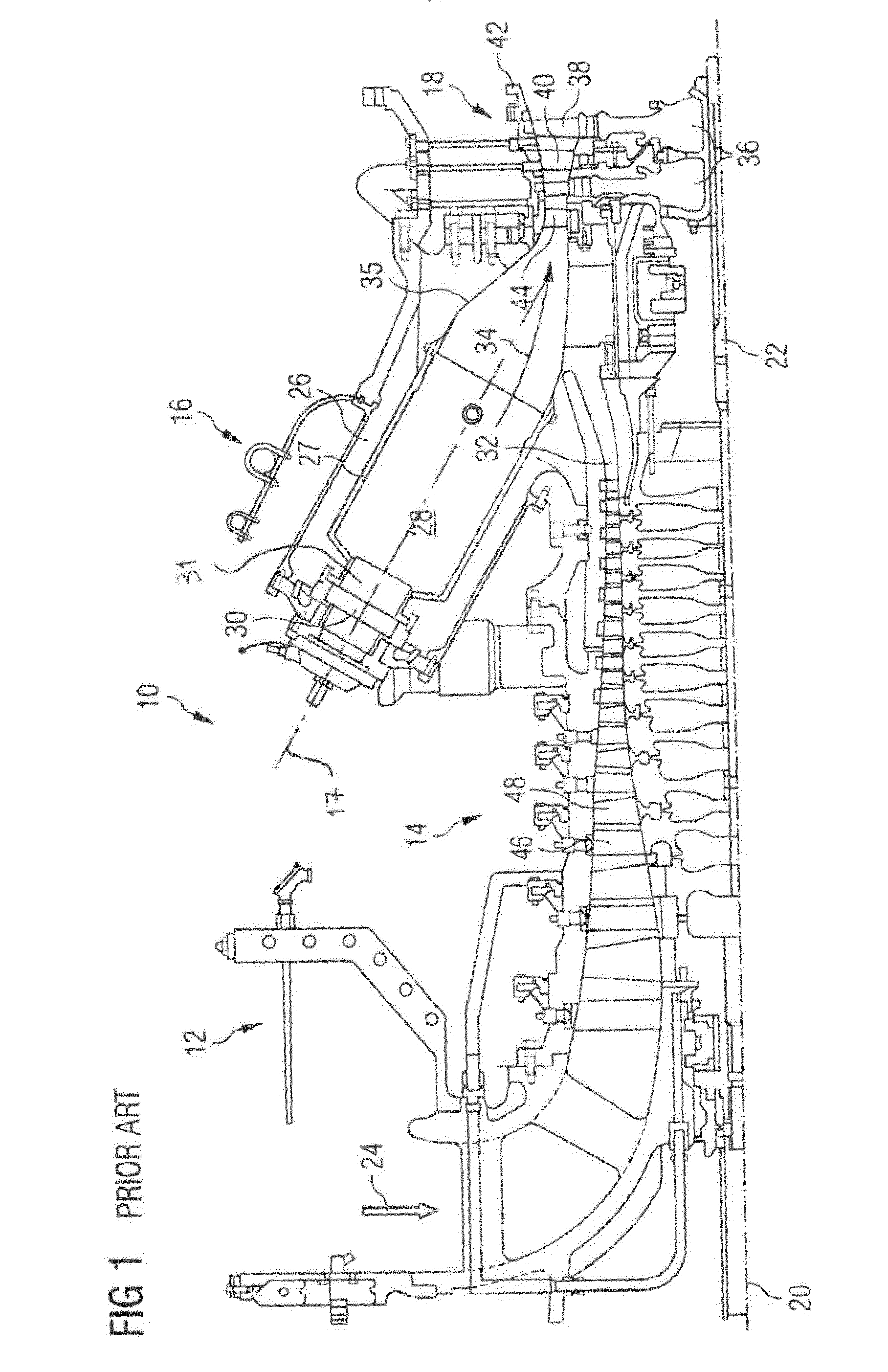
[0029]Elements having the same functions and mode of action are provided in FIGS. 1, 2a, b and 3a, b, c with the same reference signs.

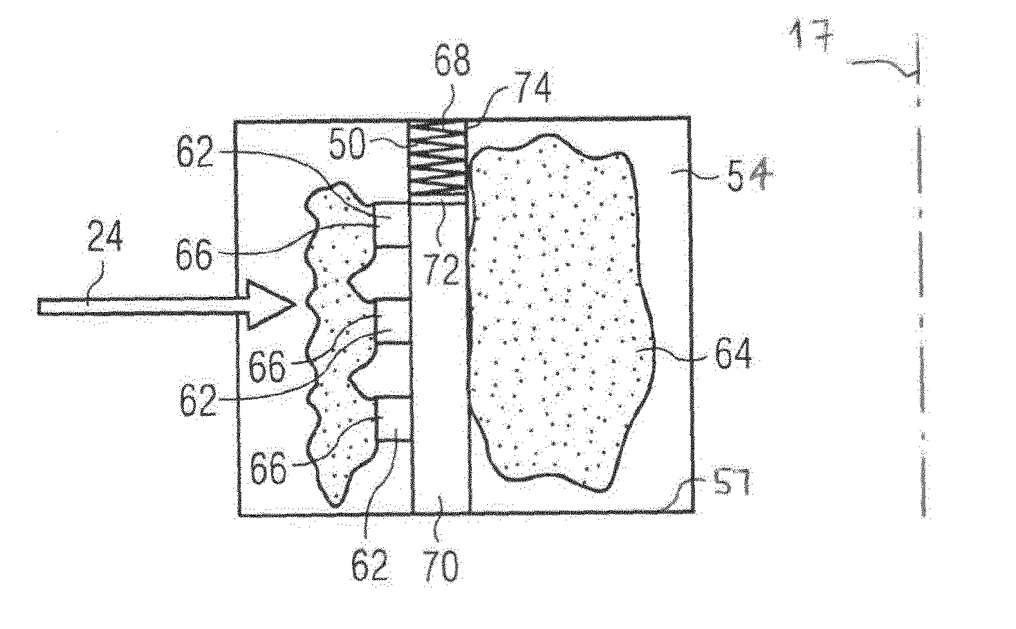
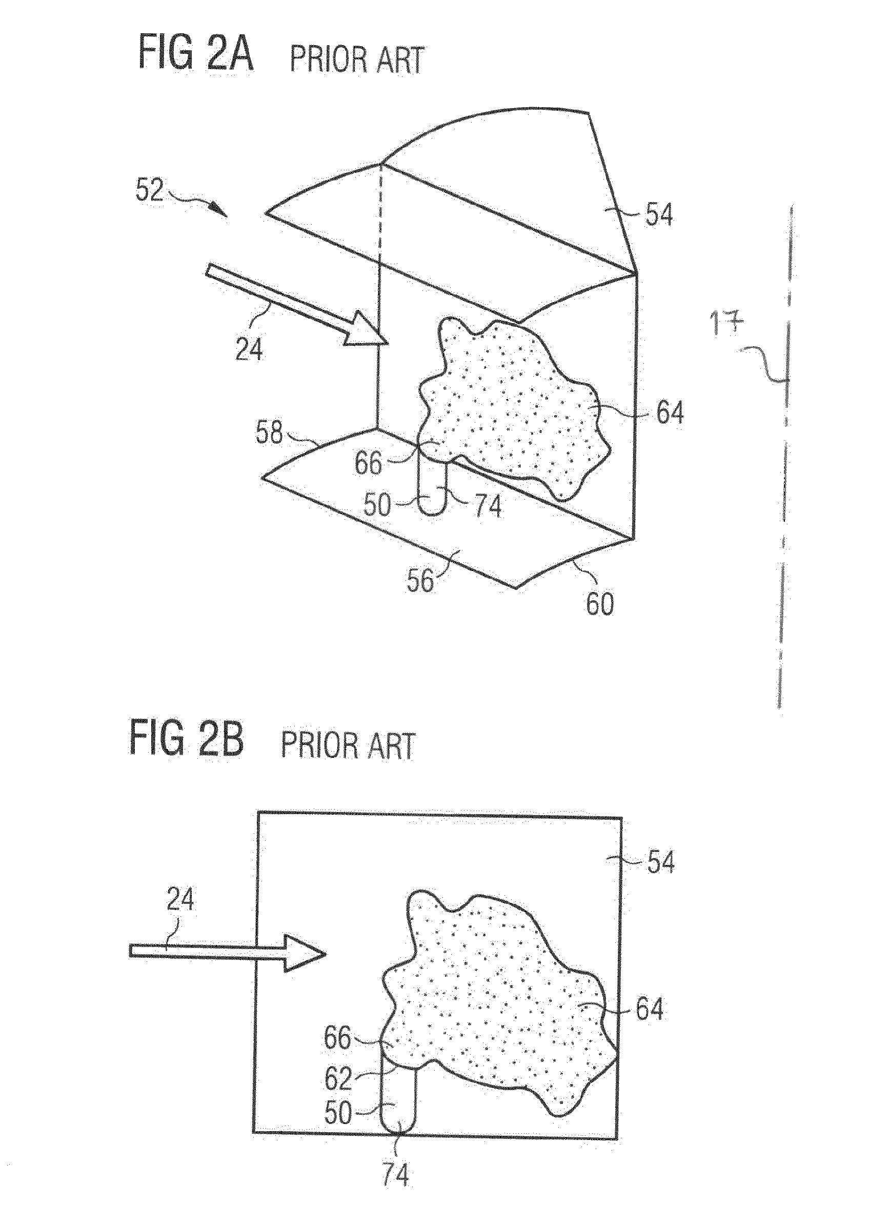
[0030]In FIG. 2a, 2b parts of a swirler 52 according to prior art are shown. In detail, one of the vanes 54 and a mixing channel 56 is shown. In the mixing channel 56 air 24 is channelled from a radially outer end 58 to a radially inner end 60 of the mixing channel 56. Inside the mixing channel 56 a fuel injection means 50 is placed. This fuel injection means 50 is in this embodiment constructed as a fuel injection lance 74. At the end of the fuel injection lance 74 an injection port 62 is located. Through this injection port 62 a fuel injection 66 of fuel 64 into the air 24 is carried out. The shown fuel injection lance 74 is optimized and designed for a full load operation of the gas turbine engine 10. Therefore, at part load operations of the gas turbine engine less fuel 64 is injected 66 into the air 24. An atomization of the complete fuel 64 cann...


PUM


Abstract

A fuel injection structure for a swirler of a burner of a gas turbine engine, wherein the swirler includes a plurality of vanes and a plurality of mixing channels between the vanes to channel air from a radially outer end of the mixing channel to a radially inner end of the mixing channel, of the fuel injection structure which includes at least two injection ports to inject fuel into the channeled air. A swirler for a burner of a gas turbine engine, and a burner of a gas turbine engine and a gas turbine engine includes the fuel injection structure.

Description

CROSS REFERENCE TO RELATED APPLICATIONS[0001]This application is the US National Stage of International Application No. PCT / EP2015 / 051612 filed Jan. 27, 2015, and claims the benefit thereof. The International Application claims the benefit of European Application No. EP14154756 filed Feb. 11, 2014. All of the applications are incorporated by reference herein in their entirety.FIELD OF INVENTION[0002]The present invention is related to a fuel injection means for a swirler of a burner of a gas turbine engine, the swirler comprising a plurality of vanes and a plurality of mixing channels between the vanes to channel air from a radially outer end of the mixing channel to a radially inner end of the mixing channel, the fuel injection means comprising at least two injection ports to inject fuel into the channelled air. Further, the invention is related to a swirler for a burner of a gas turbine engine, comprising fuel injection means, a plurality of vanes and plurality of mixing channels ...

Claims


Application Information

Patent Timeline
IPC IPC(8): F23R3/28F23R3/14
CPCF23R3/14F23R3/286F23D11/26F23D2900/00016
Inventor BULAT, GHENADIE
Owner SIEMENS AG
Why Eureka
Try Eureka