Surveying Instrument

a technology of scanning instruments and inclination sensors, applied in the direction of instruments, surveying with inclination sensors, using reradiation, etc., can solve the problems of high cost of equipment, and high cost of equipmen

Active Publication Date: 2016-12-01
KK TOPCON
View PDF0 Cites 16 Cited by
  • Summary
  • Abstract
  • Description
  • Claims
  • Application Information

AI Technical Summary

Benefits of technology

[0021]Furthermore, according to the present invention, in the surveying instrument, the horizontal rotating unit is a horizontal rotating mechanism unit as provided on a total station and the two

Problems solved by technology

Therefore, a plurality of surveying instruments are necessary and an equipment cost becomes expensive.
In par

Method used


Image

  • Surveying Instrument
  • Surveying Instrument
  • Surveying Instrument

Examples


first embodiment

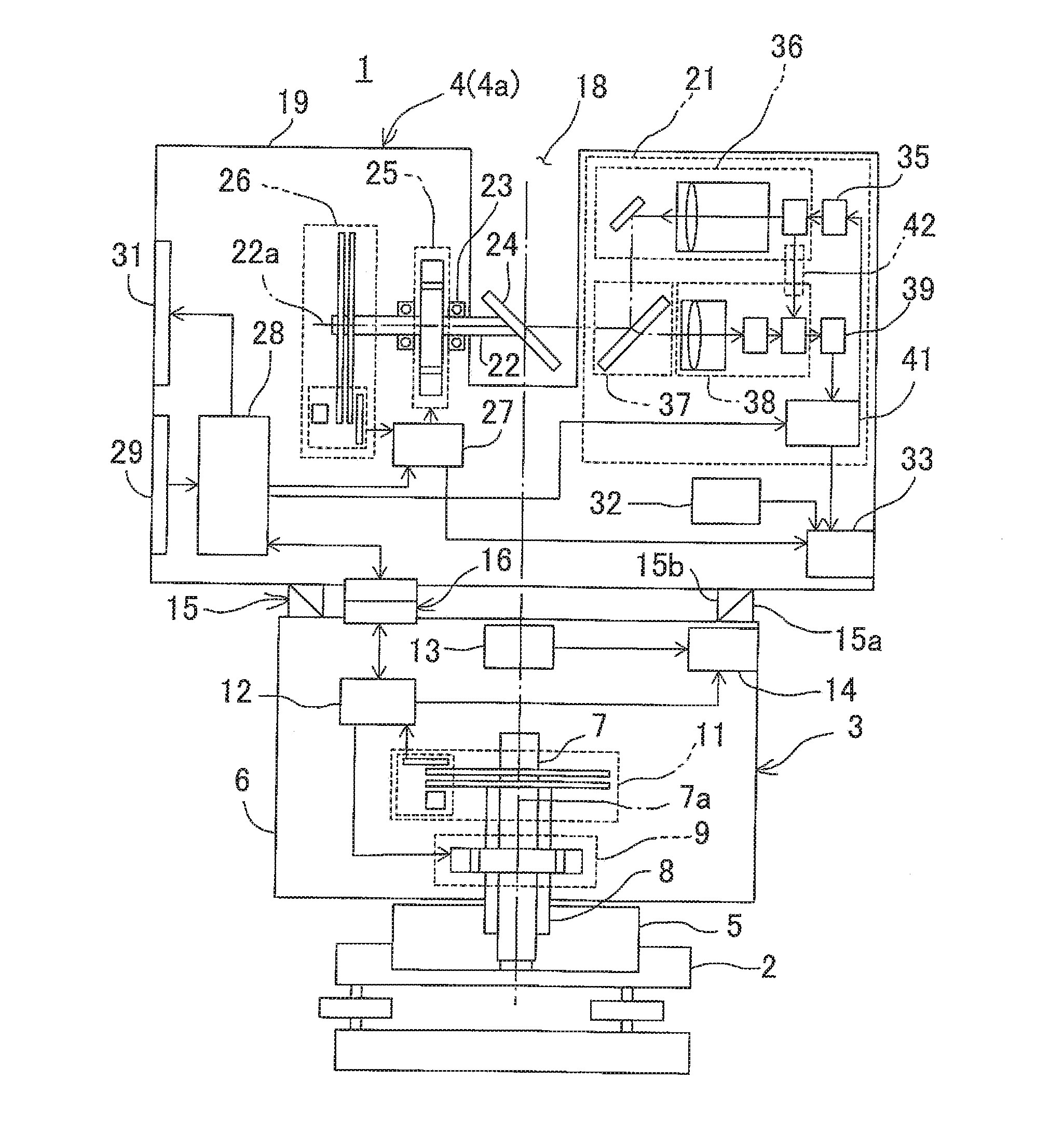
[0027]First, referring to FIG. 1, a description will be given on a

[0028]The first embodiment shows a case when arranged as a surveying instrument 1 with a function of a laser scanner.

[0029]The surveying instrument 1 primarily comprises a leveling unit 2 mounted on a tripod (not shown), a horizontal rotating unit 3 provided on the leveling unit 2 and a measuring unit 4, which is removably installed on the horizontal rotating unit 3. In the first embodiment, the measuring unit 4 is designed as a two-dimensional scanner unit 4a.

[0030]The horizontal rotating unit 3 comprises a fixing unit 5, a horizontal rotating body 6, a horizontal rotation shaft 7, a horizontal rotation bearing 8, a horizontal rotating motor 9, a horizontal angle encoder 11 serving as a horizontal angle detector, a horizontal angle control unit 12, a first synchronization data generating unit 13, a first storage unit 14, etc.

[0031]The horizontal rotation bearing 8 is fixed on the fixing unit 5, the horizontal rotati...

second embodiment

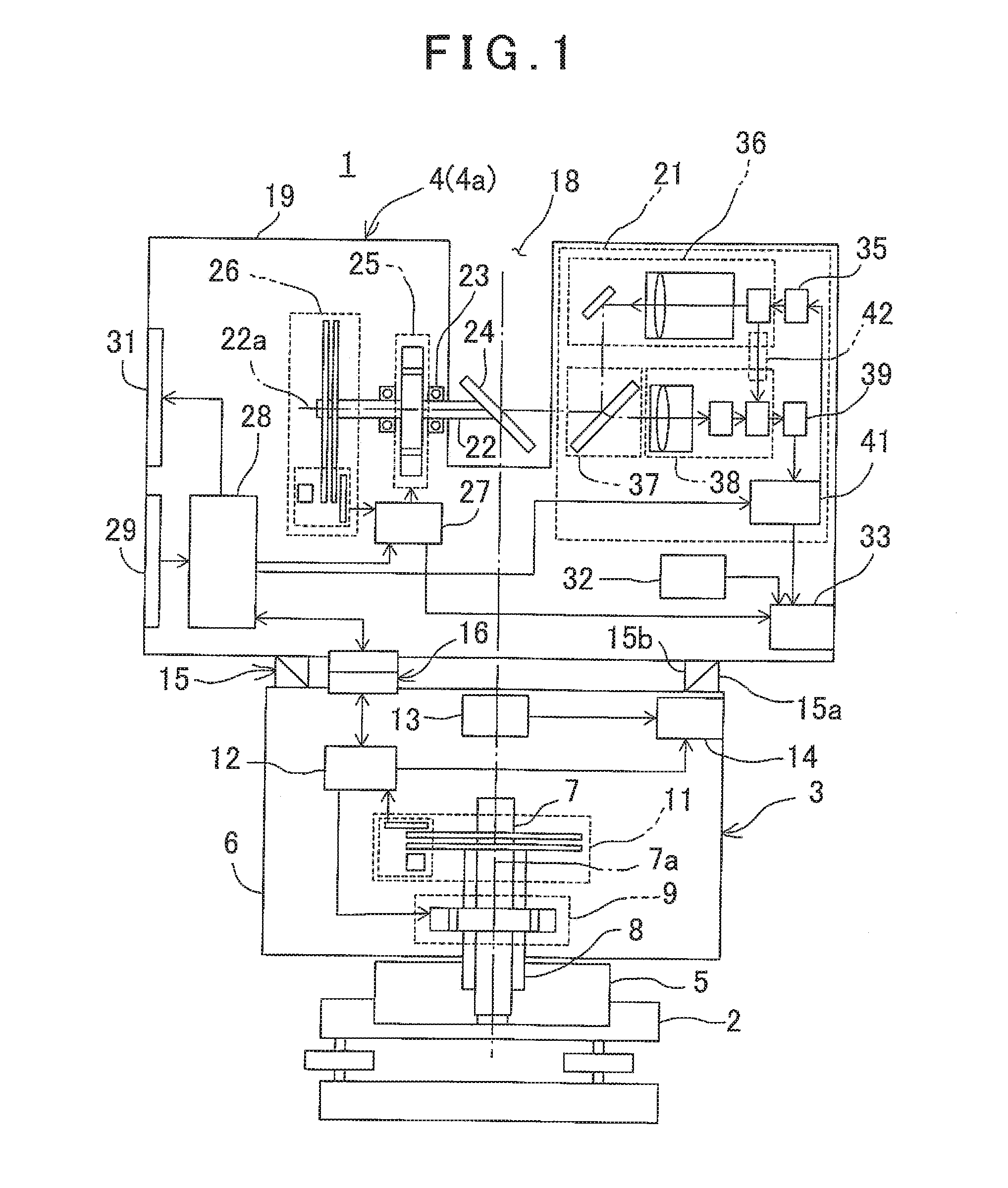
[0088]Referring to FIG. 2, a description will be given on a

[0089]The second embodiment shows a surveying instrument 1 which is constituted so as to have a function of a total station.

[0090]It is to be noted that in FIG. 2, what are equivalent to components as shown in FIG. 1 are referred by the same symbol, and detailed description thereof will be omitted.

[0091]On a horizontal rotating unit 3, a sighting distance measuring unit 45 is mounted as a measuring unit 4 via a coupler 15. The sighting distance measuring unit 45 has a sighting telescope 57 and is capable of distance-measuring a predetermined measuring point with high accuracy.

[0092]A recessed portion 48 is formed on a housing 47. A vertical rotation shaft 51 is rotatably mounted on the housing 47 via a bearing 49.

[0093]The vertical rotation shaft 51 has a horizontal axis 51a, one end portion is extended into the recessed portion 48 and a telescope unit 52 is fixed on the one end portion. On the other end of the vertical rota...

third embodiment

[0112]FIG. 3 shows a

[0113]The third embodiment shows a case where a surveying instrument 1 is constituted to have a function of a total station and a function of a laser scanner.

[0114]It is to be noted that in FIG. 3, what are equivalent to components as shown in FIG. 1 and FIG. 2 are referred by the same symbol, and detailed description thereof will be omitted.

[0115]A sighting distance measuring unit 45 is installed on an upper surface of a horizontal rotating unit 3 via a coupler 15. The horizontal rotating unit 3 and the sighting distance measuring unit 45 are electrically connected by a connector 16.

[0116]Further, a two-dimensional scanner unit 4a is installed on an upper surface of the sighting distance measuring unit 45 via a coupler 15′. The coupler 15′ has the same structure as that of the coupler 15, the coupler 15′ couples the sighting distance measuring unit 45 with the two-dimensional scanner unit 4a and also performs an alignment of the sighting distance measuring unit ...


PUM


Abstract

The invention provides a surveying instrument, which comprises a horizontal rotating unit and a measuring unit installed on the horizontal rotating unit, wherein the horizontal rotating unit comprises a driving unit for rotating the measuring unit, a horizontal angle detector for measuring horizontal angle data, a first synchronization data generating unit, a first storage unit and a first control unit, wherein the first synchronization data generating unit outputs first synchronization data which indicate a timing at a time of acquisition of the horizontal angle data of the horizontal angle detector, the first control unit associates the horizontal angle data with the first synchronization data and stores in the first storage unit, wherein the measuring unit comprises a distance measuring unit for performing a distance measurement, a vertical angle detector for detecting a vertical angle at a time of distance measurement, a second synchronization data generating unit, a second storage unit and a second control unit, wherein the measuring unit acquires two-dimensional measurement data based on distance measurement data by the distance measuring unit and vertical angle data by the vertical angle detector, the second synchronization data generating unit outputs second synchronization data which indicate timings of a time of acquisition of the distance measurement data and a time of acquisition of the vertical angle data, the second control unit associates the two-dimensional measurement data with the second synchronization data and stores in the second storage unit, and the horizontal angle data and the two-dimensional measurement data can be converted to three-dimensional data based on the first synchronization data and the second synchronization data.

Description

BACKGROUND OF THE INVENTION[0001]The present invention relates to a surveying instrument, by which it is possible to perform measurements in different modes of measurement such as a measurement of a point to be measured or an acquisition of a point cloud data of an object to be measured, and the like.[0002]Conventionally, a total station is used in a case where a measurement of a point to be measured is performed and a laser scanner is used in a case where a shape of an object to be measured is to be determined. The laser scanner determines the shape of the object to be measured as a group of innumerable points with coordinates.[0003]Since measurement methods of the total station and the laser scanner are different, the surveying instruments do not have interchangeability, and a total station or a laser scanner was necessary, corresponding to each of the case where measurement of a point to be measured is performed or the case where measurement of a shape of the object to be measure...

Claims


Application Information

Patent Timeline
IPC IPC(8): G01C15/00G01S17/42G01S17/02G01S17/86
CPCG01C15/008G01S17/42G01S17/023G01B11/24G01C15/002G01S7/4813G01S7/4817G01S17/86
Inventor KUMAGAI, KAORUYOSHINO, KEN-ICHIRO
Owner KK TOPCON
Why Eureka
Try Eureka