
Location estimation in a communication network

a communication network and location estimation technology, applied in the field of location estimation in a communication network, can solve the problems of limited accuracy of the method of location estimation, and achieve the effect of accurate static characteristic location estimation, computational efficiency and memory efficiency

Active Publication Date: 2016-12-01
VODAFONE IP LICENSING
View PDF4 Cites 4 Cited by
  • Summary
  • Abstract
  • Description
  • Claims
  • Application Information

AI Technical Summary

Benefits of technology

The patent text describes a method for more accurately estimating the location of a device in a wireless network. This is done by combining the event frequencies from different cells and sectors, rather than simply selecting the cell with the most frequent events. This approach takes into account the relative importance of different parts of the network, resulting in a more accurate and efficient way of locating devices. This technique can be used with large amounts of data and does not require any additional sensors.

Problems solved by technology

The LTE wireless interface is incompatible with 2G and 3G networks, so it is operated on a separate wireless spectrum.
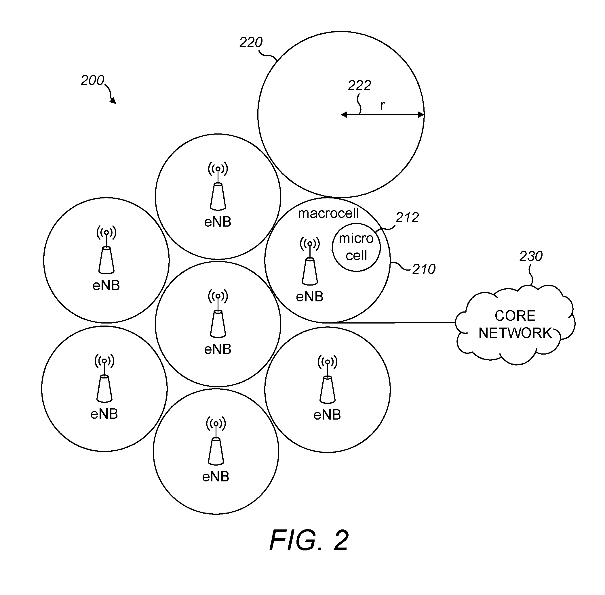
However, this method of location estimation has limited accuracy because it estimates the same location for all mobile terminals connected to the same cell i.e., the centre of the predicted coverage area of the cell commonly referred to as the cell centroid.

Method used


Image

  • Location estimation in a communication network
  • Location estimation in a communication network
  • Location estimation in a communication network

Examples


first embodiment

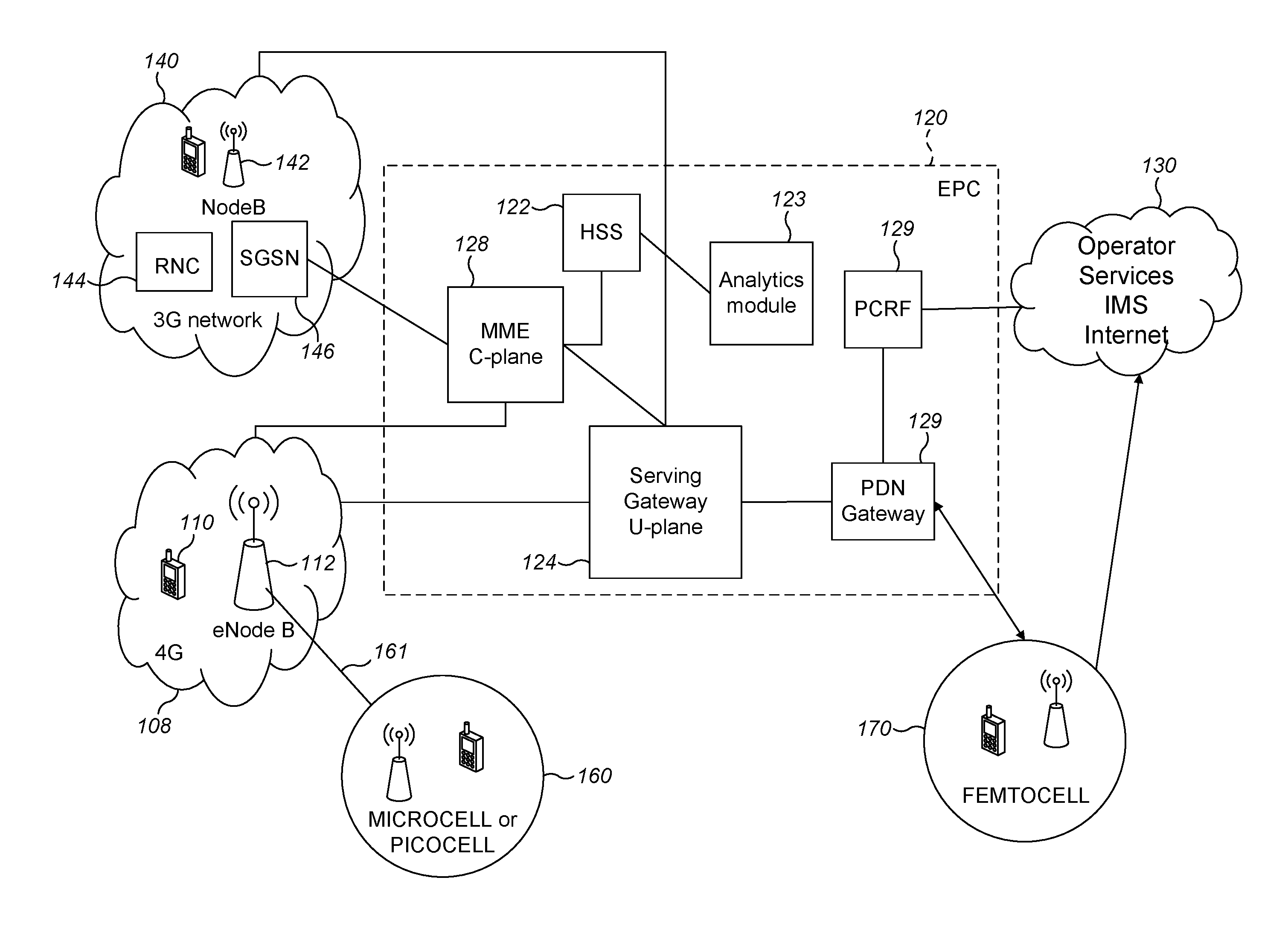
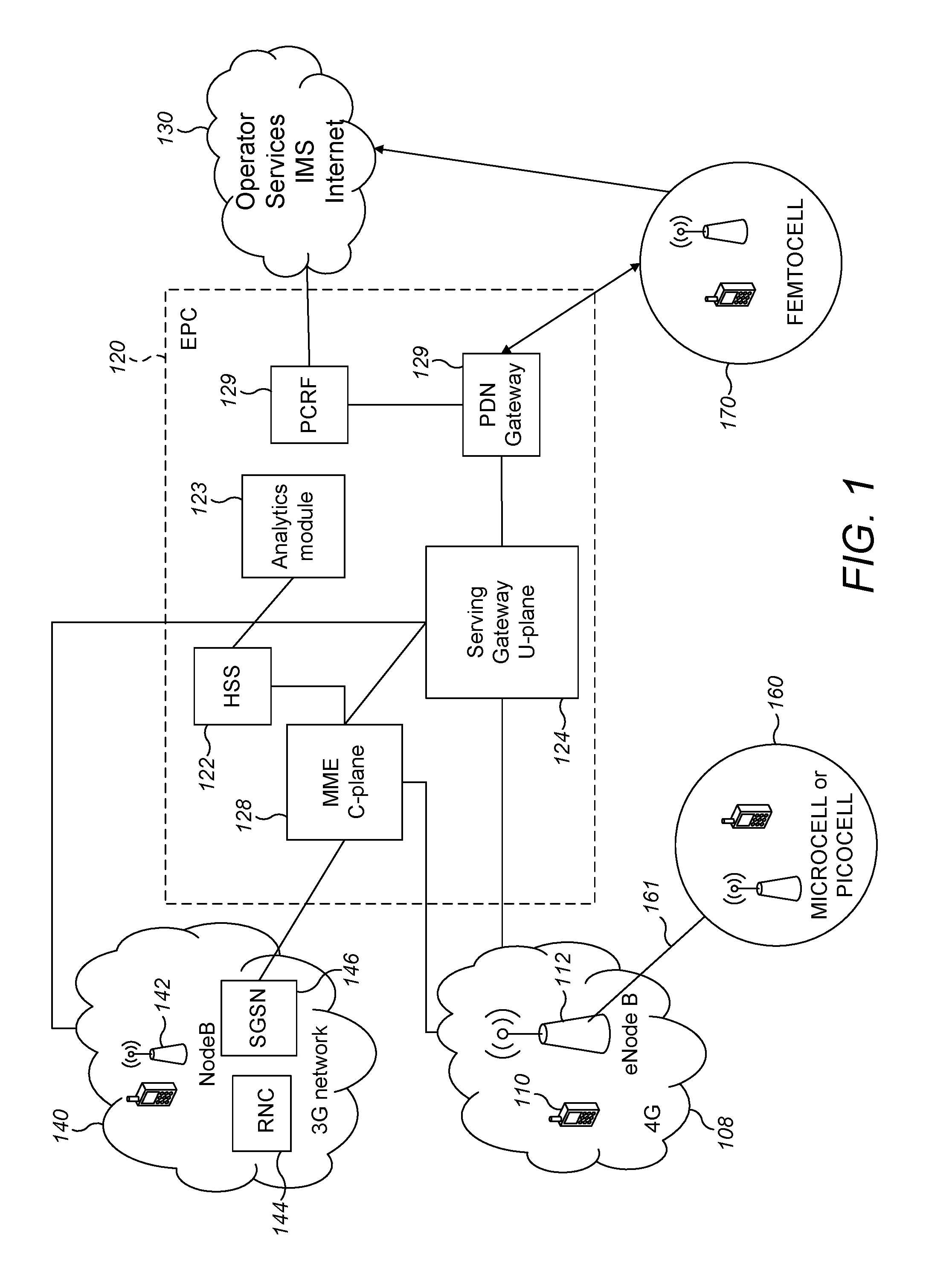
[0089]FIG. 6 is a flow chart that schematically illustrates a method of static location estimation by an analytics engine according to a The method starts at a process element 610 and proceeds to a process element 620, where the system accesses network data relating to eNodeB coverage areas (cells and sectors) including cell IDs, cell radii and cell centroids. Each coverage area (cell or sector) is uniquely identifiable for a given PLMN based upon the cell ID. Next, at process element 630, the analytics engine accesses the HSS (122) and / or other network sources of UE location events, such as the CDF and CGF and UE History Information. Once the UE location event observations have been obtained, the process proceeds to a process element 650, where the cell (or sector or coverage area) having the highest number of observed events in a given time period is identified as the highest incidence cell. When the time period corresponds to an overnight period, this relates to determining a st...

second embodiment

[0097]FIG. 8 is a flow chart that schematically illustrates a method of static location estimation by the analytics module according to a Process elements 810, 820, 830 and 840 of FIG. 8 correspond respectively to process elements 610, 620, 630 and 640 of the flow chart of FIG. 6 and the same processes are performed as described above in relation to FIG. 6. However, the process of FIG. 8 differs from that in FIG. 6, because at process element 850 a calculation different from the threshold comparison of FIG. 6 process element 650 is performed. In particular, at process element 850, the location event data for the UE is analysed to identify all cells, other than the highest incidence cell identified at process element 840, having one or more events in a given time period. At least a subset, comprising an integer number N of these identified cells is selected for inclusion in the refined static location calculation. For example, the subset of N cells having at least some overlap in co...


PUM


Abstract

A method, apparatus and computer program are provided for estimating a characteristic static location of a user equipment in a wireless communication network comprising a plurality of network nodes for transmitting radio signals. Each network node has an associated cell corresponding to a predicted geographical coverage area of a corresponding transmitted radio signal. Location event data for the user equipment provides a cell-specific location for the user equipment at a point in time. A plurality of event frequencies is determined for the user equipment, each corresponding to a cumulative number of received location events locating the user equipment in a respective cell / sector in a given time interval. A characteristic static location is calculated using a combined measure of at least two non-zero values of the plurality of event frequencies corresponding respectively to at least two different cells or sectors.

Description

FIELD OF THE INVENTION[0001]The present invention relates to an apparatus, method and computer program for static location estimation of mobile terminals in a communication network.BACKGROUND OF THE INVENTION[0002]Cellular telecommunications networks characteristically provide “cells” of radio communication coverage between communication devices (which are typically mobile) and a core network (with a “downlink” from core network to communication device and an “uplink” in the opposite direction).[0003]Various radio access technologies (RATs) are implemented: currently digital cellular networks are the most common and these are loosely classed as second generation (2G), third generation (3G), fourth generation (4G), etc. technologies according to whether the RAT achieves effective data communications that meet increasingly challenging requirements. Included in the 4G standards are the third generation partnership project (3GPP) long term evolution (LTE) and LTE-Advanced (LTE-A), which...

Claims


Application Information

Patent Timeline
Patent Type & Authority Applications(United States)
IPC IPC(8): G01S5/02G01S5/00H04W4/029
CPCG01S5/0027G01S5/0294H04W64/00G01S11/08G01S5/0278H04W4/029G01S5/00G01S5/0295H04W4/02
Inventor LUDDEN, BRENDAN
Owner VODAFONE IP LICENSING
Learn More