Laser safety glasses with an improved imaging system

a technology of safety glasses and laser radiation, applied in the direction of optical elements, mechanical pattern conversion, instruments, etc., can solve the problems of laser radiation injury, eye injuries, thermal damage,

Active Publication Date: 2016-12-01
LUMENIS LTD
View PDF4 Cites 9 Cited by
  • Summary
  • Abstract
  • Description
  • Claims
  • Application Information

AI Technical Summary

Benefits of technology

[0015]In another aspect, the information the system generates and provides to the wearer may include one of more parameters of: energy level of system, pulse width of a laser energy source operatively connected to the system, graphical or textual information related to the patient, images of the medical or cosmetic site, the position of a aiming laser beam, instructions for the procedure, patient body vital information or status of the laser as being on or off.
[0016]In a further aspect, a sending unit may be operatively associated with the glasses to project one or more images of information onto the screen. The sending unit might be connected in one of wired or wireless to a programmed controller of the system. A virtual controller allows the wearer to control specified parameters of the system generated on the screen by one or more of movement or position of one or more body organ such as a finger, hand, foot, eye lid, pupil or other.
[0017]In yet a further aspect, one or more sensors mounted on the glasses detect the one or more of movement or position of the one or more fingers on the wearer's hands. The detection of one or more of movement or position by the one or more sensors causes the virtual controller to control said certain parameters.
[0018]In another aspect, the laser safety glasses further may include a foot switch to activate

Problems solved by technology

Laser light may cause eye injuries and therefore safety measures are involved with laser applications.
Thermal damage is the predominant cause of laser radiation injury.
However, photochemical or shock waves associated with cavitation may also injure the eye tissue.
Light visible to near infrared wavelengths can penetrate the cornea and the lens of the eye and may damage the ret

Method used


Image

  • Laser safety glasses with an improved imaging system
  • Laser safety glasses with an improved imaging system
  • Laser safety glasses with an improved imaging system

Examples


Embodiment Construction

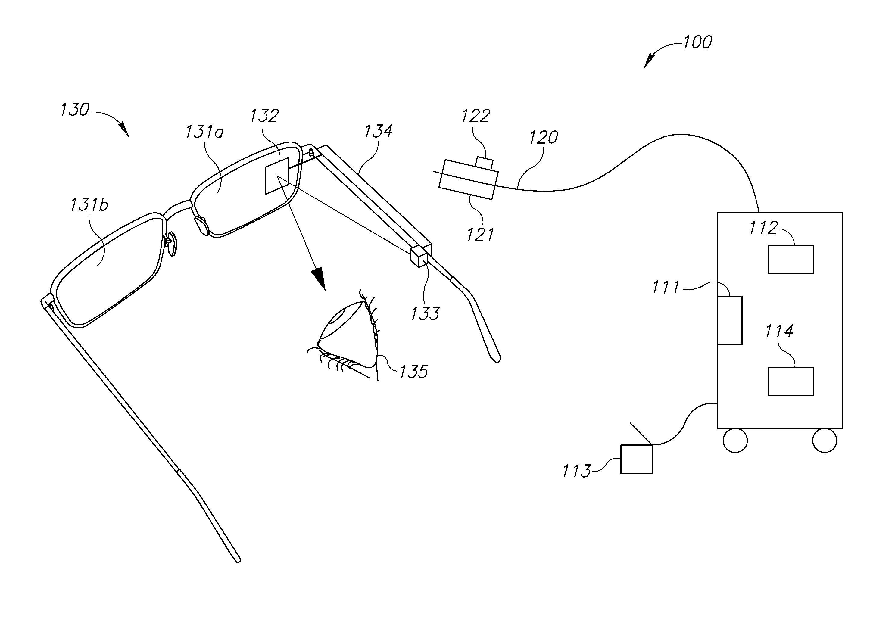
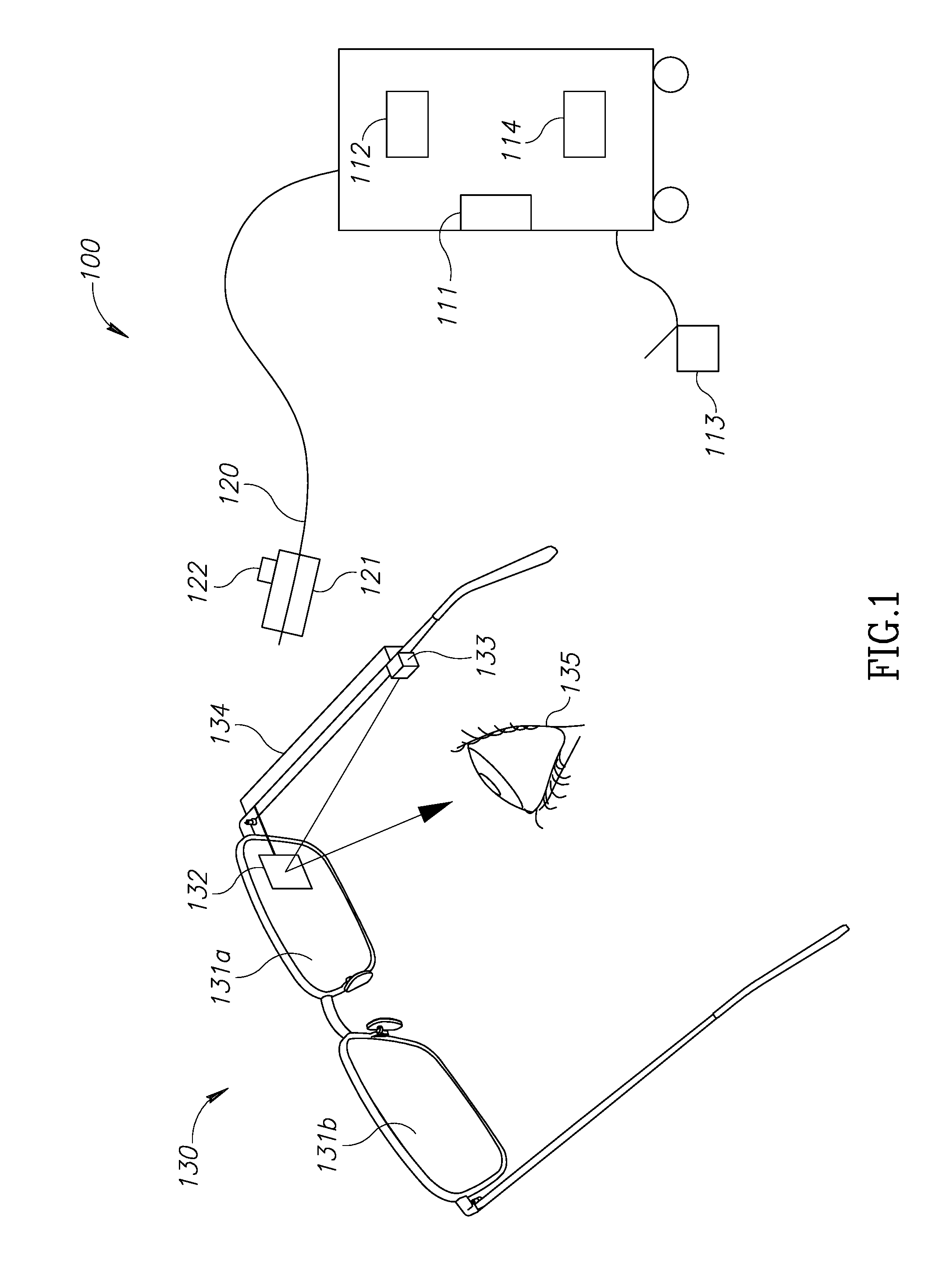
[0024]According to one aspect of the invention there is provided laser safety glasses which include enhanced imaging capabilities. Referring to FIG. 1, a laser system 100 is shown. Laser system 100 comprises a laser console 110 having laser delivery system 120. Laser system 110 may be for example a solid state laser such as for example NdYAG, Holmium, or Erbium. Alternatively, such a laser system may be, for example, a gas-fired laser such as a CO2, a diode laser, Alexandrite, Ruby or a fiber laser. In addition, laser 110 may be configured to generate more than one wavelength. Laser delivery systems may include, for example, an optical fiber, a wave guide or an articulated arm.

[0025]Laser system 100 further includes glasses or goggles 130 having lenses 131a and 131b which are configured to protect the operator's eye 135 by filtering laser wavelength or wavelengths generated by laser 110 and transmitted by or through delivery system 120 onto a surgical site. At least one lens 131a or...


PUM


Abstract

Laser safety glasses for use in laser medical and cosmetic procedures on a patient include a pair of safety glasses wherein the safety glasses include a pair of lenses, one or more of the lenses being structured to absorb one or more predetermined wavelengths of laser energy light; a screen is mounted on at least one lens of the pair of lenses, the screen being operatively associated with a system one of internal or external to the glasses configured to generate and provide information regarding the medical or cosmetic procedure to a wearer of the laser safety glasses through the screen.

Description

RELATED APPLICATIONS[0001]This application is related to and claims priority to U.S. Provisional Application Ser. No. 62 / 166,188, filed May 26, 2015, the entirety of which disclosure is herein incorporated by reference.BACKGROUND OF THE PRESENT INVENTION[0002]In recent years there is a growing presence of lasers in operating rooms and points of care. The proliferation of laser technologies into the medical field is driven by a wide diversity of better and cheaper laser generators and delivery systems. The availability and reliability of these technologies further expose more researchers and practitioners to their potential contribution in medicine and more laser applications are developed.[0003]Laser light may cause eye injuries and therefore safety measures are involved with laser applications. Laser tissue interaction is a function, among other things, of the laser wavelength. Thermal damage is the predominant cause of laser radiation injury. However, photochemical or shock waves ...

Claims


Application Information

Patent Timeline
IPC IPC(8): G02C11/00G02C7/10G06F3/01G06K9/00G06T19/00A61F9/02G02B27/01
CPCG02C11/10A61F9/022G02C7/10G02B2027/0178G06K9/00671G06T19/006G06F3/017G02B27/0172G02B5/22G02B2027/0187G06F3/011G06F3/04847
Inventor WAISMAN, TALELAZAR, MOSHECHOBOTARU, OFERPREISS, ASSAF
Owner LUMENIS LTD
Why Eureka
Try Eureka