Dual path timing wander removal

a dual-path, time-varying technology, applied in the field of jitter, can solve problems such as systematic jitter, system performance cannot be guaranteed, jitter caused by gaps in downstream systems, etc., and achieve the effect of reducing wander

Active Publication Date: 2016-12-01
SKYWORKS SOLUTIONS INC
View PDF2 Cites 26 Cited by
  • Summary
  • Abstract
  • Description
  • Claims
  • Application Information

AI Technical Summary

Benefits of technology

[0012]In another embodiment, a phase-locked loop (PLL) includes a time to digital converter circuit to generate a timing difference between a first signal based on a time stamp associated with a packet-based network and a second signal. An excursion detector receives the timing difference and supplies as an excursion detector output a first adjustment if a magnitude of the timing difference is above a predetermined threshold and otherwise supplies a second adjustment of zero. A low pass filter receives the excursion detector output and supplies a low pass filtered output of

Problems solved by technology

However, transport networks may also insert systematic jitter in timing signals by, e.g., inserting gaps in clocks to align input and output data.
The drawback of using the gapped clock technique, however, is the jitter caused by the gaps for the downstream system.
Since the gap patterns are very unpredictable and difficult to model and characterize, system performance cannot be guaranteed.
That is one reason gapped clock techniques are not widely used despite the cleanness in system partitioning afforded by gapped clocks.
Other drawbacks of gapped clock use is that low bandwidth jitter cleaning, which is sensitive to temperature fluctuations, has excessive system respon

Method used


Image

  • Dual path timing wander removal
  • Dual path timing wander removal
  • Dual path timing wander removal

Examples


Embodiment Construction

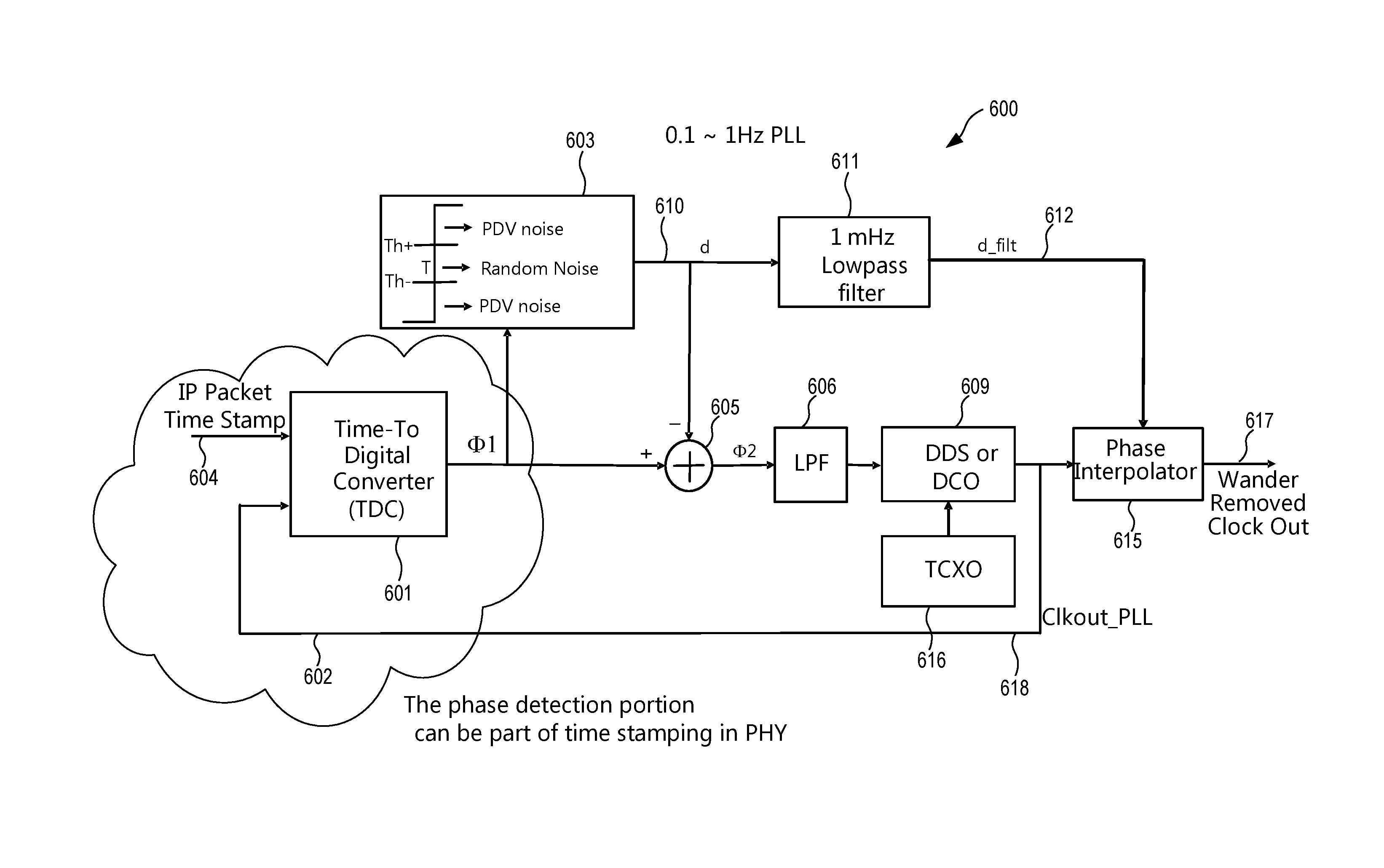
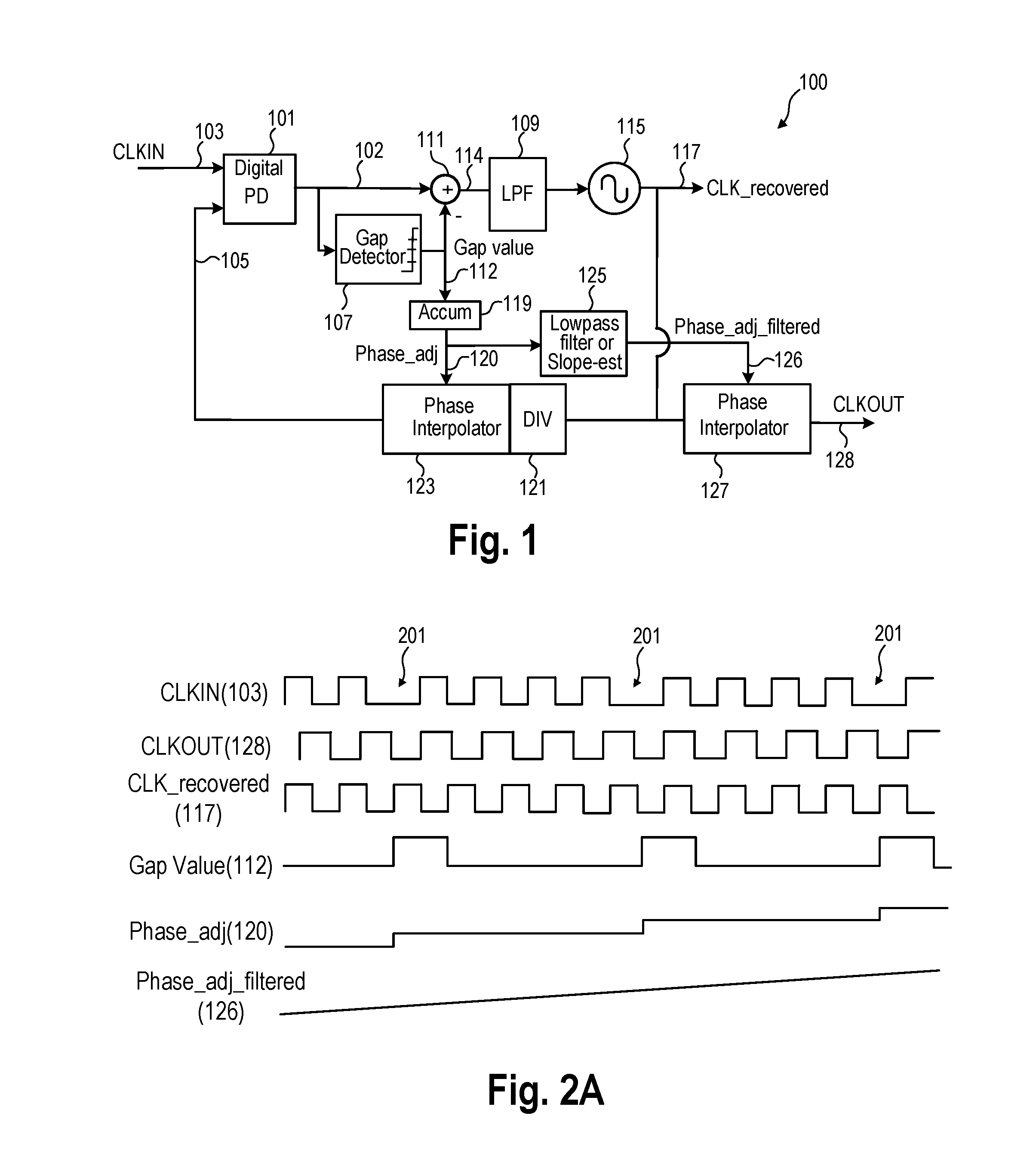
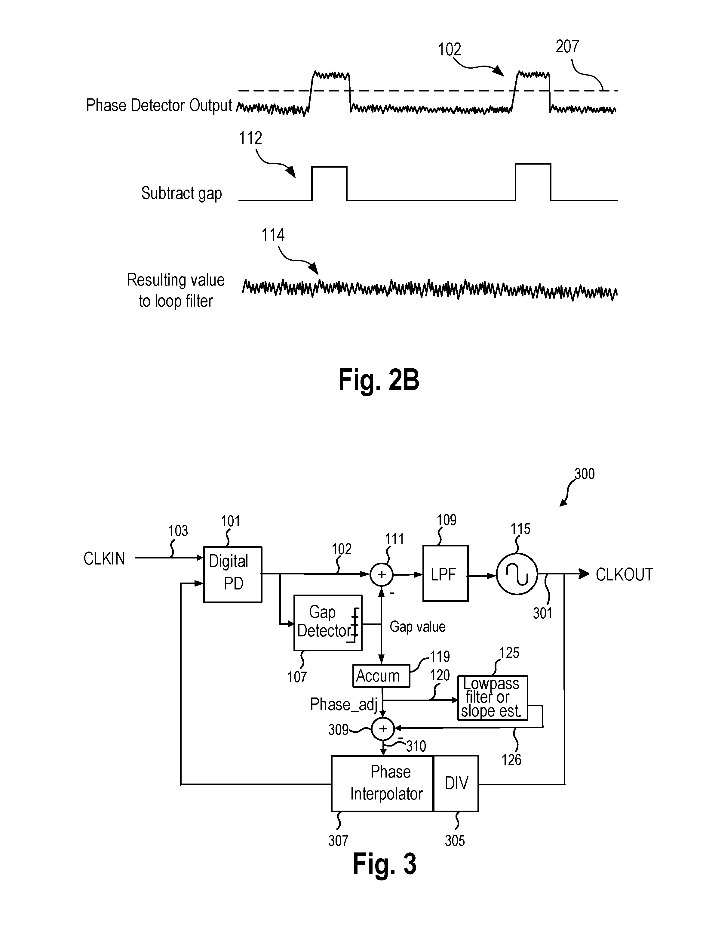
[0010]In an embodiment, a method includes determining a timing difference between a first signal and a second signal and supplying the timing difference. An excursion detector detects if a magnitude of the timing difference is above a predetermined timing threshold and supplies as an excursion detector output a first adjustment if a magnitude of the timing difference is above the predetermined threshold and otherwise supplies as the excursion detector output a second adjustment. An arithmetic circuit receives the excursion detector output and adjusts the timing difference by the first or the second adjustment. A loop filter receives an output of the arithmetic circuit. An oscillator is controlled based on the loop filter output and supplies an oscillator output signal. An output of the excursion detector is low pass filtered.

[0011]In another embodiment an apparatus includes an excursion detector that is coupled to receive a timing difference between a first signal and a second signa...


PUM


Abstract

A more cost effective wander jitter filter utilizes an excursion detector that receives a timing difference between a first signal and a second signal and supplies a first adjustment amount if a magnitude of the timing difference is above a predetermined threshold and otherwise supplies a second adjustment amount of zero. A summing circuit adjusts a magnitude of the timing difference by the first or second adjustment amount. A loop filter receives the summing circuit output and controls an oscillator. The excursion detector output (first adjustment value or zero according to the magnitude of the timing difference) is low pass filtered and the low pass filtered is reintroduced into the oscillator output or the feedback loop. The excursion detector output is accumulated and used to adjust a phase of the feedback signal from the oscillator.

Description

CROSS REFERENCE TO RELATED APPLICATIONS[0001]This application is a continuation-in-part of application Ser. No. 14 / 725,053 filed May 29, 2015, entitled “Dual Path Timing Jitter Removal”, naming Yunteng Huang as inventor, which application is incorporated herein by reference in its entirety.BACKGROUND[0002]1. Field of the Invention[0003]The invention relates to jitter and more particularly to dealing with jitter that contains large jitter due to packet delay variations relative to random jitter.[0004]2. Description of the Related Art[0005]Optical transport networks (OTNs), broadcast video, and other applications use timing signals as part of the system to transport payloads. Such timing signals include a signal component caused by random or thermal related jitter. Thus, timing signals for one part of the system are nominally, but not exactly the same as timing signals for another part of the system. Phase-locked loops (PLLs) have traditionally been used to deal with the random jitter...

Claims


Application Information

Patent Timeline
IPC IPC(8): H04L7/033H03L7/093H03L7/091H04L27/227H04J3/06
CPCH04L7/0332H04L27/2272H03L7/093H03L7/091H04J3/0661H03L7/0994H03L7/0805H03L7/081H03L7/085H03L7/0991H04L7/002
Inventor HUANG, YUNTENG
Owner SKYWORKS SOLUTIONS INC
Why Eureka
Try Eureka