
Method for operating a base station in a wireless radio network

a wireless radio network and wireless radio technology, applied in the direction of wireless communication, transmission monitoring, baseband system details, etc., can solve the problems of significant deterioration, and achieve the effect of reducing the amount of overhead data to be transmitted, reducing the amount of overhead data, and facilitating the operation

Inactive Publication Date: 2016-12-01
SONY CORP
View PDF4 Cites 8 Cited by
  • Summary
  • Abstract
  • Description
  • Claims
  • Application Information

AI Technical Summary

Benefits of technology

This approach reduces overhead by optimizing the timing and frequency of training signal transmission, improving system throughput and payload capacity by minimizing the header size relative to payload, while maintaining high data communication quality.

Problems solved by technology

However, when there is a fast relative movement determined between the base station and the user equipment, for example when the base station is arranged stationary and the user equipment is moving along in a vehicle, a significant deterioration is expected when the user equipment is moving out of the focus of the antennas of the base station defined by the configuration parameters.

Method used


Image

  • Method for operating a base station in a wireless radio network
  • Method for operating a base station in a wireless radio network
  • Method for operating a base station in a wireless radio network

Examples


Embodiment Construction

[0025]In the following, exemplary embodiments of the present invention will be described in more detail. It is to be understood that the features of the various exemplary embodiments described herein may be combined with each other unless specifically noted otherwise. Same reference signs in various drawings refer to similar of identical components. Any coupling between components or devices shown in the figures may be a direct or an indirect coupling unless specifically noted otherwise.

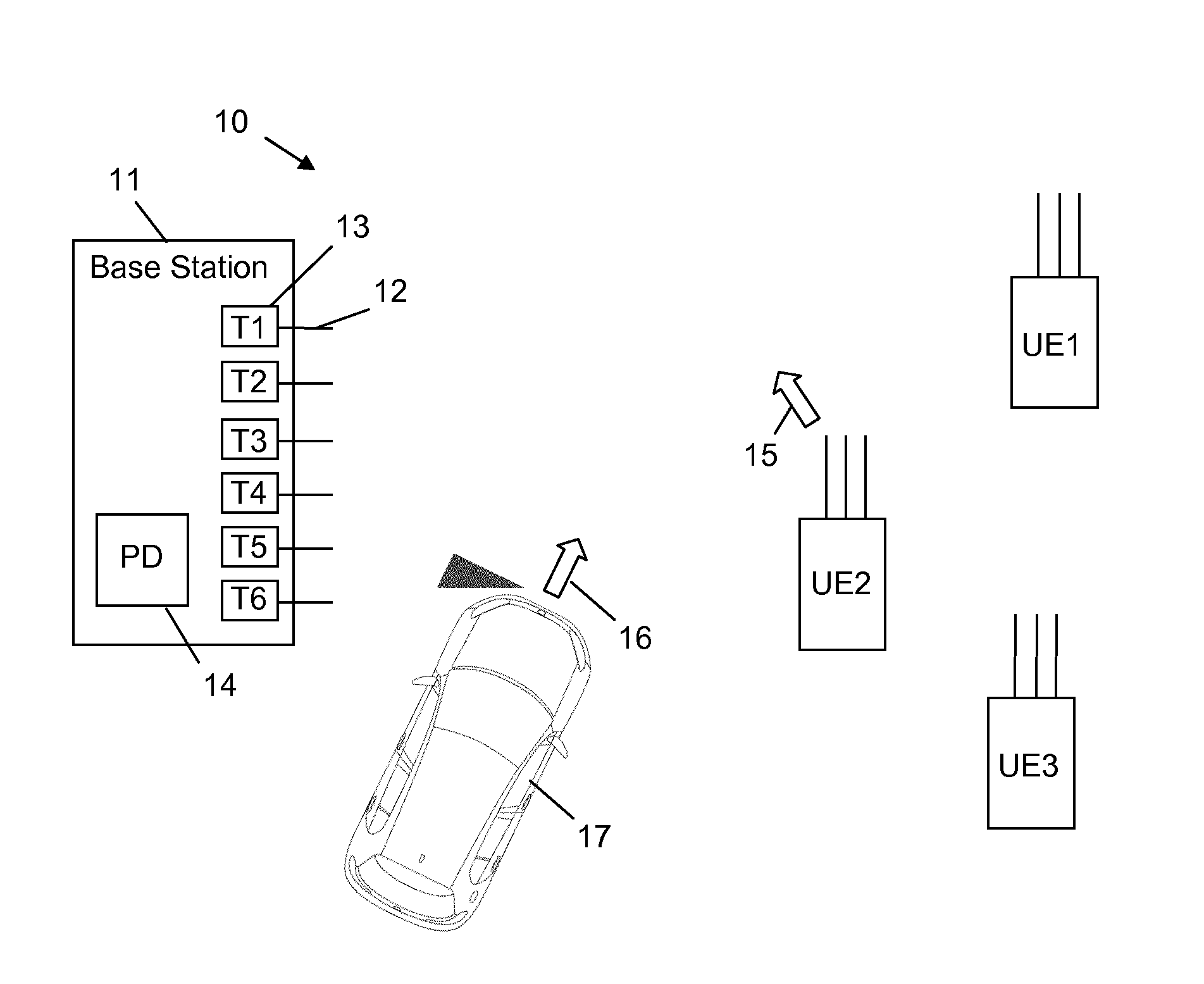
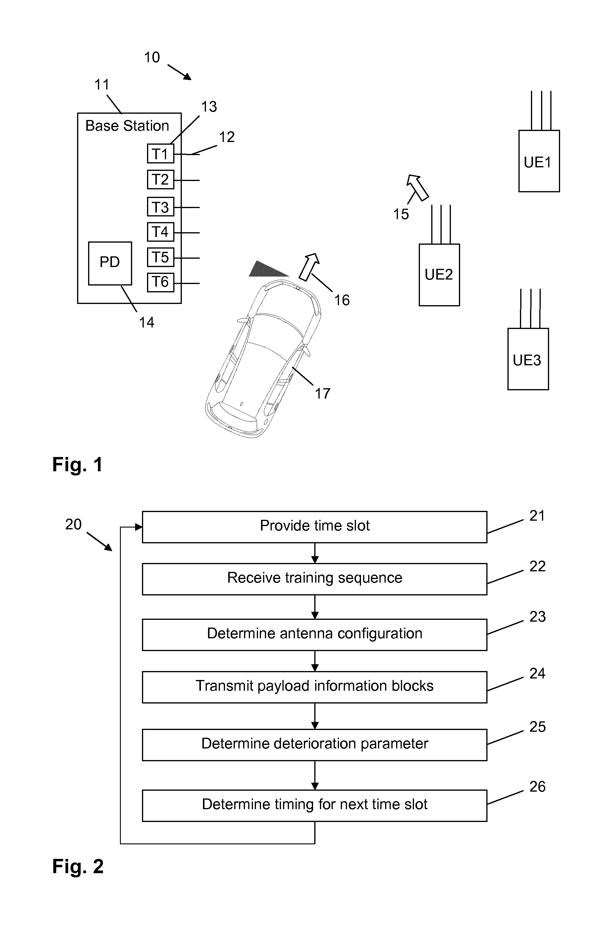
[0026]FIG. 1 shows three user equipments UE1, UE2 and UE3 arranged in an environment 10 of a base station 11. The base station 11 comprises a plurality of antennas 12 and associated transceivers 13. In FIG. 1 only six antennas 12 and six transceivers 13 are shown for clarity reasons. However, these are only exemplary numbers and the base station 11 may comprise for example an array of 30 to 100 or even more antennas and associated transceivers arranged for example in a matrix or cylindrically. Likewi...


PUM


Abstract

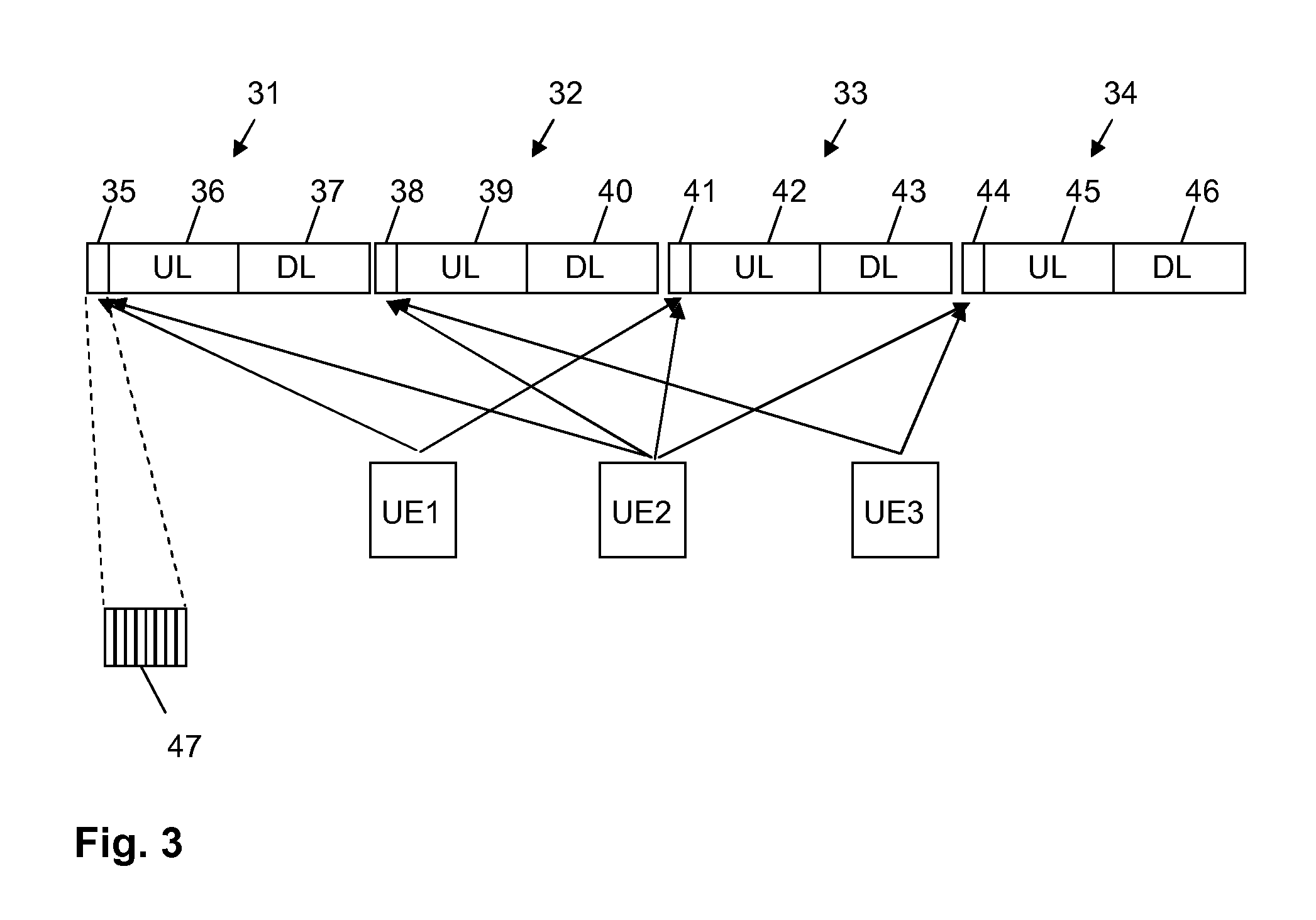
The present invention relates to a method for operating a base station (11) in a wireless radio network (10). The base station (11) comprises a plurality of antennas (12) for transmitting radio frequency signals between the base station (11) and a user equipment (UE1, UE2, UE3). According to the method, a transmission slot (47) is provided for receiving at each antenna (12) of a subset of the plurality of antennas (12) a training signal sent from the user equipment (UE1, UE2, UE3). For each antenna (12) a corresponding configuration parameter is determined based on the training signal received at the corresponding antenna (12) and payload information blocks (36, 37) to be transmitted between the base station (11) and the user equipment (UE1, UE2, UE3) are transmitted using the determined configuration parameters for the antennas (12). A deterioration parameter indicating a deterioration of a transmission between the base station (11) and the user equipment (UE1, UE2, UE3) due to a change in the transmission requiring adaption of the configuration parameters is determined. Based on the deterioration parameter, a timing parameter is determined for controlling when a further transmission slot (47) is to be provided for receiving at each antenna (12) a next training signal sent form the user equipment (UE1, UE2, UE3).

Description

FIELD OF THE INVENTION[0001]The present invention relates to a method for operating a base station in a wireless radio network. Especially, the present invention relates to a method for operating a base station comprising a plurality of antennas for transmitting radio frequency signals according to a so-called multiple-input and multiple-output (MIMO) technology. The present invention relates furthermore to a base station which implements the method, and a user equipment which is configured to be used in connection with the base station.BACKGROUND OF THE INVENTION[0002]For increasing data transmission performance and reliability, the so-called multiple input and multiple-output technology (MIMO) may be used in wireless radio frequency telecommunications for transmitting information between a base station and a user equipment. The MIMO technology relates to the use of multiple send and receive antennas for a wireless communication at for example a base station or a user equipment. Th...

Claims


Application Information

Patent Timeline
Patent Type & Authority Applications(United States)
IPC IPC(8): H04W28/12H04B17/318H04W72/04H04B17/336H04B7/04H04W4/02H04W4/029
CPCH04W28/12H04B7/0452H04W4/027H04W4/028H04B17/318H04W4/026H04W72/0446H04B17/336H04W4/02H04B7/0874H04L25/0204H04L25/0226H04L25/0222H04W4/029H04B7/0456
Inventor LARSSON, BOYING, ZHINONGBENGTSSON, ERIK
Owner SONY CORP
Learn More