Body lumen fluid delivery device

a delivery device and body lumen technology, applied in the direction of ultrasonic/sonic/infrasonic image/data processing, applications, applications, etc., can solve the problems of damage to the body, no means to concentrate the medication, and the delivery device wall hole does not provide an image viewable area, so as to avoid jetting and pressure damage

Active Publication Date: 2016-12-08
ATRIUM MEDICAL
View PDF1 Cites 1 Cited by
  • Summary
  • Abstract
  • Description
  • Claims
  • Application Information

AI Technical Summary

Benefits of technology

This patent is for a fluid delivery device that can navigate through difficult body anatomy to deliver fluids to target treatment locations. The device has a flexible conduit with micro-lumens that allow for real-time visualization of the injected fluid during delivery. The device can deliver multiple gene therapy vectors without causing damage to nearby tissue. The technical effects of this invention include improved flexibility, torque response, and the ability to avoid pressure damage and jetting during fluid delivery.

Problems solved by technology

Placement of one or more holes along the side wall of such delivery devices have been clinically shown to cause tissue damage under injection delivery pressures, creating a damaged area within the body.
Such side wall hole delivery devices also do not provide for image viewable zones of delivery as they are indicated for systemic delivery of medication.
Non-porous elastomeric and angioplasty balloon catheters have also been used to deliver therapeutic agents directly to treatment sites within a body cavity by creating systemic occlusion of the vessel or narrow lumen with the same undesirable clinical effects when the medication is uncontrollably delivered by syringe via jetting fluid out through the central lumen of such delivery device generally located on the distal end and side holes.
Such devices provide no means to concentrate the medication without inducing either occlusion or trauma to the vessel, and without any image guidance means to determine where the concentration of medication is delivered.
A significant shortcoming common to such drug eluting porous conventional balloon catheters is that the multiple bonding zones required for attaching a porous delivery balloon to the catheter shaft, and its size, length and geometry of the balloon portion around the external shaft of the catheter limits the ability of the catheter to track around tortuous anatomy, significantly restricting access to various hard to reach and remote body cavity treatment sites for localized delivery of therapeutic agents.
For example, both conventional porous and non-porous balloon catheters may encounter difficulty accessing smaller vessel treatment sites having narrow, or partially occluded or diseased lumens leading up to the treatment site.
In addition, the sites at which conventional balloon catheters are able to be positioned for treatment are limited by the size and geometry of the folded balloon material and bonding sites on the outside of the catheter shaft.
Further, in those situations in which a balloon catheter is able to access more difficult to reach sites, or smaller sites, the expansion of the medication delivery balloon itself to release the therapeutic agent may not be able to be positioned to maximize drug concentration at the treatment site without causing damage to the narrowed channel or vessel.
In some instances, the damage may be caused by a jetting action of the fluid emitting from the balloon or delivery device and impacting the tissue.
In these situations, conventional balloon catheters therefore may not be suitable for localized delivery of therapeutic agents to many narrow, partially occluded and remote treatment sites within the body.

Method used


Image

  • Body lumen fluid delivery device
  • Body lumen fluid delivery device
  • Body lumen fluid delivery device

Examples


Embodiment Construction

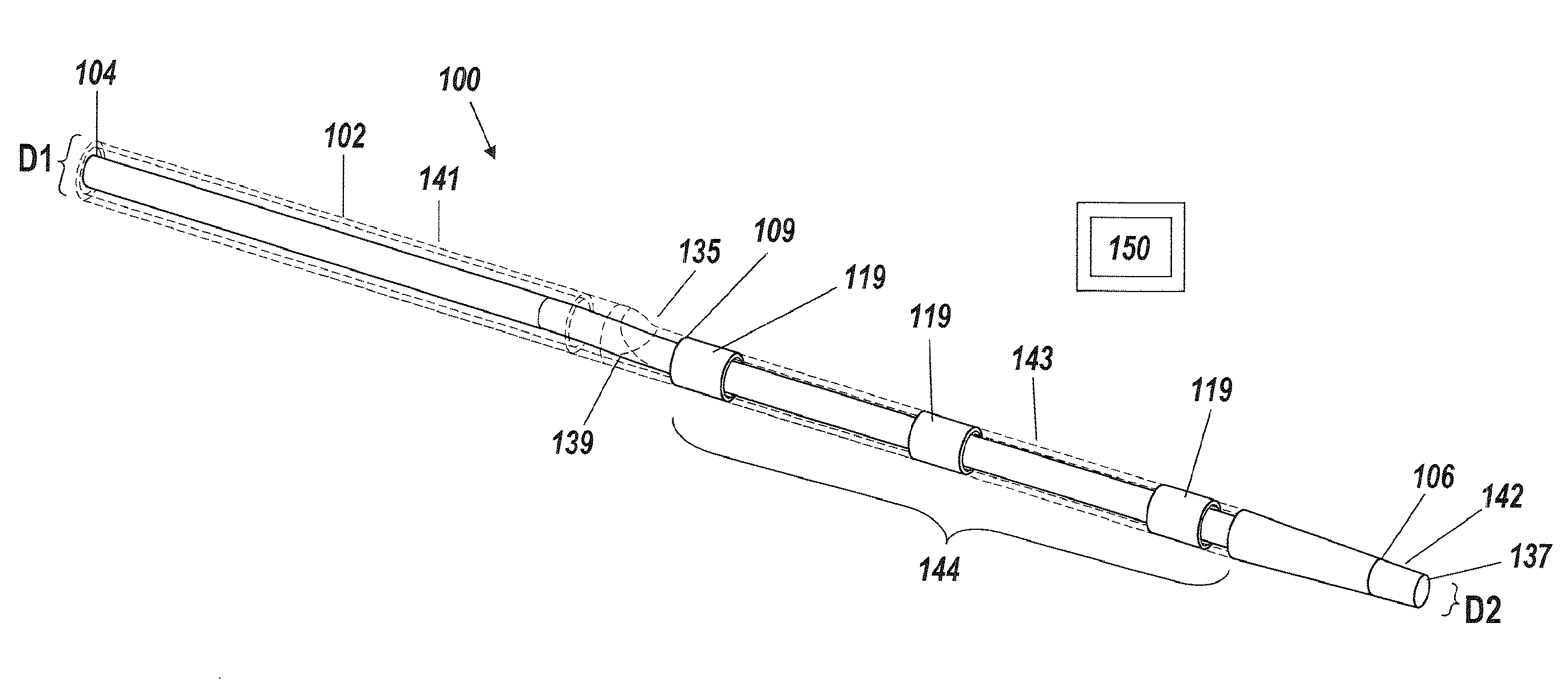
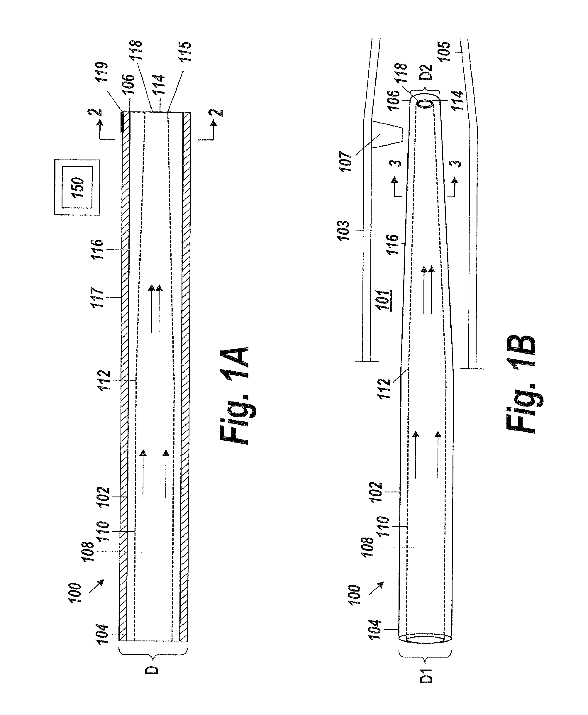
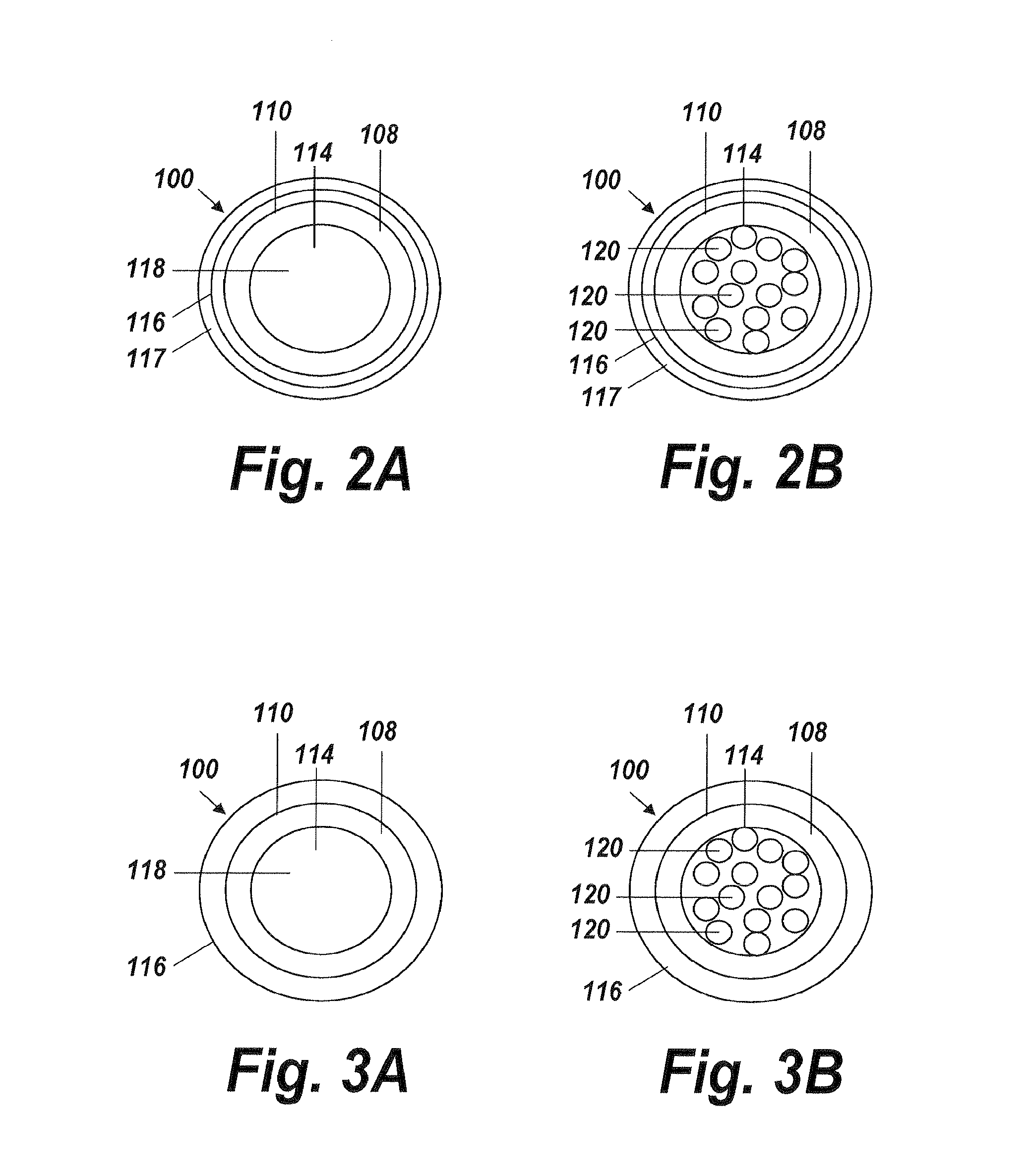
[0042]An illustrative embodiment of the present invention relates to use of a fluid delivery device structured to navigate tortuous, spatially restricted body anatomy having narrow body channel diameters (e.g., as narrow as about 1 mm or less) for the high concentration delivery of a fluid, such as a medication, therapeutic agent, or diagnostic, to a target treatment area within the body. The present invention makes use of a biocompatible, flexible conduit having a maximum outer diameter sized in such a way as to enable navigation of narrow body channels (e.g., vessels), and a micro-lumen terminating within an image viewable zone along the flexible conduit provided with a pre-determined cross-sectional flow area for continuous localized delivery of high concentrations of the fluid to fill the entire treatment area within the narrow body channel around the outside of the image viewable zone along the flexible conduit at a pressure sufficient to minimize and or avoid damage to surroun...


PUM


Abstract

A method and apparatus for fluid delivery enables navigation through tortuous, spatially restricted body anatomy to access narrow diameter body lumens for the continuous delivery of fluids, including therapeutic fluids, to the lumen in an atraumatic manner that avoids damage to the body lumen. The fluid delivery device can have a flexible conduit having a proximal end, a distal end, and a lumen extending along an interior of the flexible conduit providing a fluid flow path between the proximal and distal ends, where the lumen transitions into a micro-lumen exiting through a port through which a high concentration of fluid injected into the lumen exits laterally out along an image viewable zone at the distal end of the flexible conduit. The flexible conduit has a maximum outer diameter sized sufficient to navigate narrow diameter body lumens.

Description

RELATED APPLICATION[0001]This application is a continuation of U.S. application Ser. No. 13 / 232,340, filed Sep. 14, 2011, which claims priority to, and the benefit of, co-pending U.S. Provisional Application No. 61 / 492,439, filed Jun. 2, 2011, for all subject matter common to both applications. The disclosure of said provisional application is hereby incorporated herein by reference in its entirety.FIELD OF THE INVENTION[0002]The present invention relates to a fluid delivery device suitable for delivering a fluid to a treatment site within a patient's body, and more particularly to an image guided fluid delivery device for navigating tortuous, spatially restricted body anatomy to maintain a high concentration of a medication to a narrow diameter body lumen and within an image guided zone.BACKGROUND OF THE INVENTION[0003]In a wide range of medical treatment procedures, local therapeutic agent delivery through an open-ended delivery catheter, sheath or needle placed within a vein or a...

Claims


Application Information

Patent Timeline
Patent Type & Authority Applications(United States)
IPC IPC(8): A61M25/00A61M25/01A61B34/20A61B5/055A61B5/00A61B8/08A61M5/00A61B6/12
CPCA61M25/0068A61M2202/0007A61M25/0026A61M25/005A61M25/0108A61M25/0045A61B6/12A61B5/055A61B5/0095A61B8/0841A61B34/20A61M2025/0046A61M2025/0057A61M2202/206A61M5/007A61M25/0023A61M2025/0042A61M2025/0073A61M2025/0183A61B6/481A61B2090/3966
Inventor HERWECK, STEVE A.FURMAN, RONIT R.
Owner ATRIUM MEDICAL
Why Eureka
Try Eureka