Supercharge Your Innovation With Domain-Expert AI Agents!

Substrate polishing device and method thereof

a technology of substrate polishing and polishing device, which is applied in the direction of grinding machine, edge grinding machine, grinding machine, etc., can solve the problems of plurality of substrates having the polishing process has to be carried out more carefully, and the plurality of substrates have to be separated one by, so as to achieve uniform use

Active Publication Date: 2016-12-08
KNJ CO LTD +1
View PDF10 Cites 1 Cited by
  • Summary
  • Abstract
  • Description
  • Claims
  • Application Information

AI Technical Summary

Benefits of technology

The present invention provides a substrate polishing device and method that can polish the substrate evenly, resulting in a uniform surface. This is achieved by moving the polishing wheel at a predetermined speed in the vertical direction, allowing it to be used on the entire substrate. This results in a longer replacement period for the polishing wheel, reducing maintenance costs.

Problems solved by technology

However, if the polishing process is carried out together with the grinding process without the above-mentioned edge-removing grinding process, the polishing process has to be carried out more carefully due to the edges.
The prior art polishing system has a disadvantage that the plurality of substrates S have to be separated one by one after the polishing.
Therefore, separate slurry injection holes have to be provided in order to uniformly supply the slurry to each of the positions, resulting in the increase of the slurry consumption.
In addition, if the slurry supplied from any unnecessary parts is stuck onto the substrate, it could be a burden to the rinsing process of the substrate.
Therefore, it is not possible to process the substrate side surfaces and the edges of the substrates together.
Also, if there is a change in the size of the substrates, it could be another burden to the parts required for the stacking of the substrates such that the parts themselves should be changed.

Method used


Image

  • Substrate polishing device and method thereof
  • Substrate polishing device and method thereof
  • Substrate polishing device and method thereof

Examples


Embodiment Construction

[0038]Reference will be now made in detail to the preferred embodiments of the present invention with reference to the attached drawings.

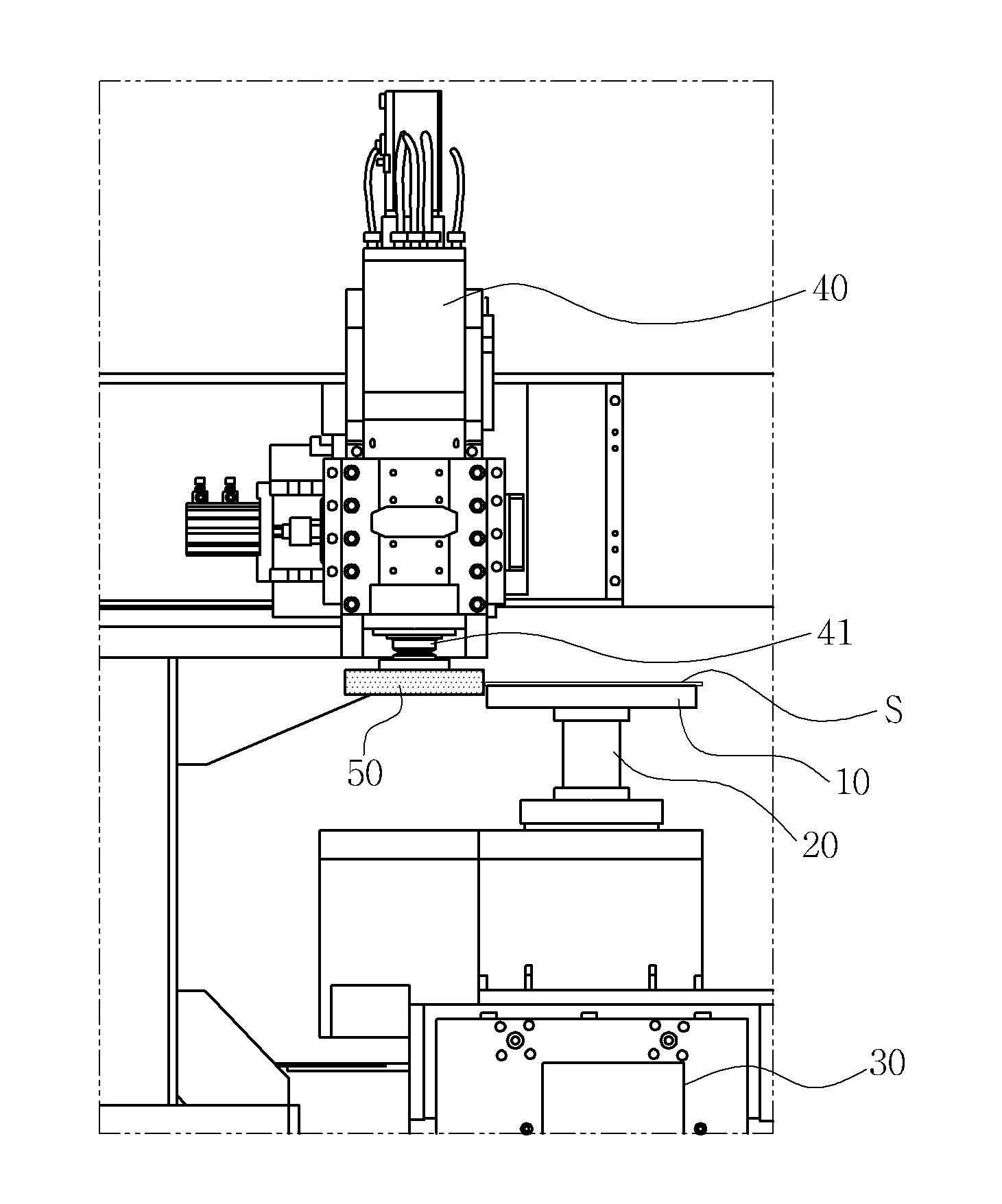
[0039]FIG. 4 is a plane view showing a substrate polishing device according to an embodiment 1 of the present invention, and FIG. 5 is a front view of the substrate polishing device. Referring to FIG. 4 and FIG. 5, a substrate polishing device according to an embodiment 1 of the present invention includes a table 10, an Y axis movement means 30, a rotation means 20, a spindle 40, a polishing wheel 50, a Z axis movement means 70 and an X axis movement means 60.

[0040]The table 10 is a constituent element for securing a substrate S and has a vacuum hole (not shown) for stably fixing the substrate by vacuum-adsorption. It is also possible to fix the substrate by means of a clamp (not shown). Meanwhile, the term “substrate” refers to all of a glass substrate, a panel or any other object to be processed.

[0041]The table 10 is rotatably provided on a rotat...


PUM


Abstract

Provided are a device and method for polishing a substrate, in which an upper ground surface, a side surface and a lower ground surface of a substrate can be simultaneously polished, and a polishing wheel can be evenly used on the whole so as to be uniformly abraded. A substrate polishing system is to polish a substrate, of which upper edge and a lower edge are polished, and includes: a table, on which the substrate is secured; a spindle provided at the upper portion of a side surface of the table; a polishing wheel formed in the shape of a cylinder and having a rotating shaft mounted perpendicularly to the substrate, so as to polish the substrate with a side surface thereof while rotating by the spindle; and a Z axis movement means for moving the polishing wheel in the vertical direction during the polishing of the substrate.

Description

BACKGROUND OF THE INVENTION[0001]Field of the Invention[0002]The present invention relates to a device and a method for polishing a substrate after grinding edges of the substrate and, more particularly, to a substrate polishing device and a substrate polishing method, in which the upper ground surface, the side surface and the lower ground surface of a substrate can be simultaneously polished, and a polishing wheel can be evenly used on the whole so as to be uniformly worn.[0003]Background Art[0004]In general, a substrate used as a panel of a flat panel display such as an LCD panel, an OLED panel and the like is cut in a certain size as necessary.[0005]In FIG. 1, (a) and (b) respectively show a substrate A. Referring to (a) and (b) of FIG. 1, the substrate A has sharp edges e1, e2 on the cut surfaces after cutting. These sharp edges e1, e2 are likely to be broken during convey, transfer or processing thereof. Therefore, in order to remove the sharp edges e1, e2, the substrate is su...

Claims


Application Information

Patent Timeline
IPC IPC(8): B24B37/20
CPCB24B37/20B24B29/00B24B41/061B24B9/00B24B9/10H01L21/02024H01L21/304
Inventor BAE, GI-HWANHONG, JUN-WOO
Owner KNJ CO LTD
Features
  • R&D
  • Intellectual Property
  • Life Sciences
  • Materials
  • Tech Scout
  • Unparalleled Data Quality
  • Higher Quality Content
  • 60% Fewer Hallucinations
Learn More