Gas Turbine Power Generation System

Inactive Publication Date: 2016-12-08
HITACHI LTD
View PDF9 Cites 15 Cited by
  • Summary
  • Abstract
  • Description
  • Claims
  • Application Information

AI Technical Summary

Benefits of technology

[0011]A gas turbine power generation system according to the present invention results an increased power capability and a fast response to adjust electric power. Therefore, s

Problems solved by technology

As the renewable energy resources have uncertainty nature, the electricity generation from the renewable energy resources has the characteristics of output power fluctuation which causes impacts on voltage stability and frequency stability of the power systems.
However, the gas turbine may suffer stress if they are operated

Method used


Image

  • Gas Turbine Power Generation System
  • Gas Turbine Power Generation System
  • Gas Turbine Power Generation System

Examples


Example

Example 1

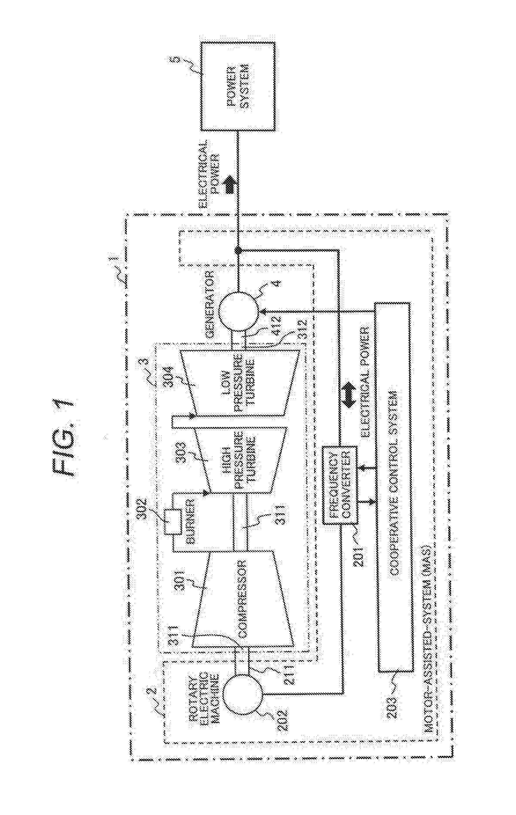
[0020]FIG. 1 illustrates an outline of a gas turbine power generation system.

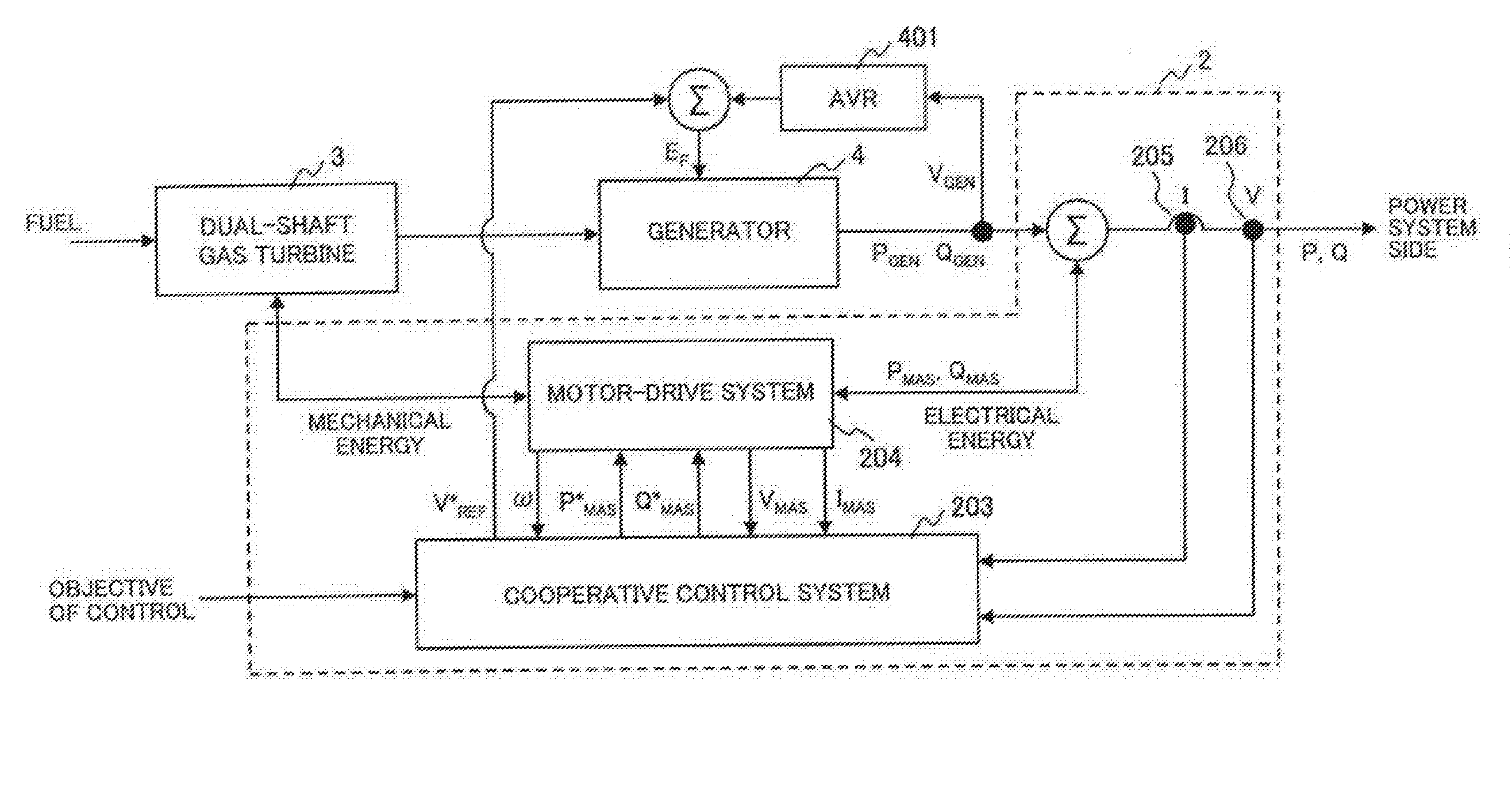
[0021]The gas turbine power generation system [1] has a motor-assisted system (MAS) [2] to adjust an electric power for a power system [5] by a rotary electric machine [202] consuming or generating an electric power, a dual-shaft gas turbine [3] and a generator [4], which outputs an electric power to the power system [5], rotating by the dual-shaft gas turbine [3].

[0022]The dual-shaft gas turbine [3] has a compressor [301], a burner [302] to make a high-temperature and high-pressure gas with burning a fuel mixing with an air compressed by the compressor [301], a high pressure turbine [303] rotating by the high-temperature and high-pressure gas, a first rotating shaft [311] connecting mechanically the high pressure turbine [303] to the compressor [301] and a low pressure turbine [304], which has a second rotating shaft [312] coupling with a rotating shaft [412] of the generator [4], rotating at a sp...

Example

Example 2

[0055]A voltage stabilization operation mode in the gas turbine power generation system [1] is explained with FIG. 5.

[0056]FIG. 5 illustrates a flowchart showing processes of the cooperative control system [203] in the voltage stabilization operation mode. Additionally, a system configuration of this embodiment is same as that of the example 1 shown by FIGS. 1-3. Components which have the same operation as shown in the Example 1 are represented with the same numbers and so the detailed explanation of those components is skipped here. Differences between the flowchart shown in FIG. 4 are mainly explained, as follows.

[0057]The objective for control in this operation mode is voltage at the power system [5] side of the GT [1]. Therefore, it is checked whether the observed voltage V meets the objective of voltage or not [203_d2].

[0058]If the observed voltage of the GT [1] does not meet the objective of voltage, a required active power and a required reactive power are determined...

Example

Example 3

[0063]A frequency stabilization operation mode in the gas turbine power generation system [1] is explained with FIG. 6. This operation mode stabilizes frequency fluctuation that happens in a power system when generation and consumption of active power in the power system is imbalanced.

[0064]FIG. 6 illustrates a flowchart showing processes of the cooperative control system [203] in the frequency stabilization operation mode. Additionally, a system configuration of this embodiment is same as that of the example 1 shown by FIGS. 1-3. Components which have the same operation as shown in the Example 1, 2 are represented with the same numbers and so the detailed explanation of those components is skipped here. Differences between the flowcharts shown in FIGS. 4 and 5 are mainly explained, as follows.

[0065]The objective for control in this operation mode is active power at the power system [5] side of the GT [1]. Therefore, it is checked whether the observed active power P meets t...


PUM


Abstract

A gas turbine power generation system has a dual-shaft gas turbine, an electric generator mechanically connected to a low pressure turbine of the dual-shaft gas turbine and electrically connected to an electric power system, a rotary electric machine mechanically connected to a high pressure turbine through a compressor of the dual-shaft gas turbine and electrically connected to the electric power system, and an electric power output from the electric generator side to the electric power system is adjusted by operation of the rotary electric machine as a motor or as a generator.

Description

TECHNICAL FIELD[0001]The present invention relates to a gas turbine power generation system contributing stability of electric power system.BACKGROUND ART[0002]Nowadays, integration of electricity generation from renewable energy resources into power systems is increasing. As the renewable energy resources have uncertainty nature, the electricity generation from the renewable energy resources has the characteristics of output power fluctuation which causes impacts on voltage stability and frequency stability of the power systems.[0003]In order to mitigate the impact of output power fluctuation, conventional generators in power systems become to have a fast load-following capability. In addition to a conventional pump-water storage hydro generator, a high-speed turbine generator such as a gas turbine generator, a steam turbine generator, can satisfy for the fast load-following capability. Due to affordable initial cost and low emissions of green house gas, the gas turbine generator c...

Claims


Application Information

Patent Timeline
IPC IPC(8): F01D15/10H02K7/18F01D5/02
CPCF01D15/10F01D5/02F05D2240/60F05D2220/32H02K7/1823F02C3/10F02C6/14F05D2220/76F05D2270/06
Inventor THET, AUNG KOHINO, NORIAKIKUSUMI, NAOHIRO
Owner HITACHI LTD
Why Eureka
Try Eureka