Rail measuring system

a measuring system and rail technology, applied in the direction of optical apparatus testing, force measurement by measuring optical property variation, instruments, etc., can solve the problem of presenting great challenges for the measuring system

Active Publication Date: 2016-12-08
THALES MANAGEMENT & SERVICES DEUT GMBH
View PDF33 Cites 22 Cited by
  • Summary
  • Abstract
  • Description
  • Claims
  • Application Information

AI Technical Summary

Problems solved by technology

For measuring systems for rail or track systems on which trains run, it is moreover a challenge to reliably detect greatly varying axle loads, in particular since the safety requirements demand a very small error rate.
This represents great challenges for a measuring system.

Method used


Image

  • Rail measuring system
  • Rail measuring system
  • Rail measuring system

Examples


Embodiment Construction

[0026]The following is a detailed description of various embodiments of the invention, wherein one or a plurality of examples are illustrated in the drawing.

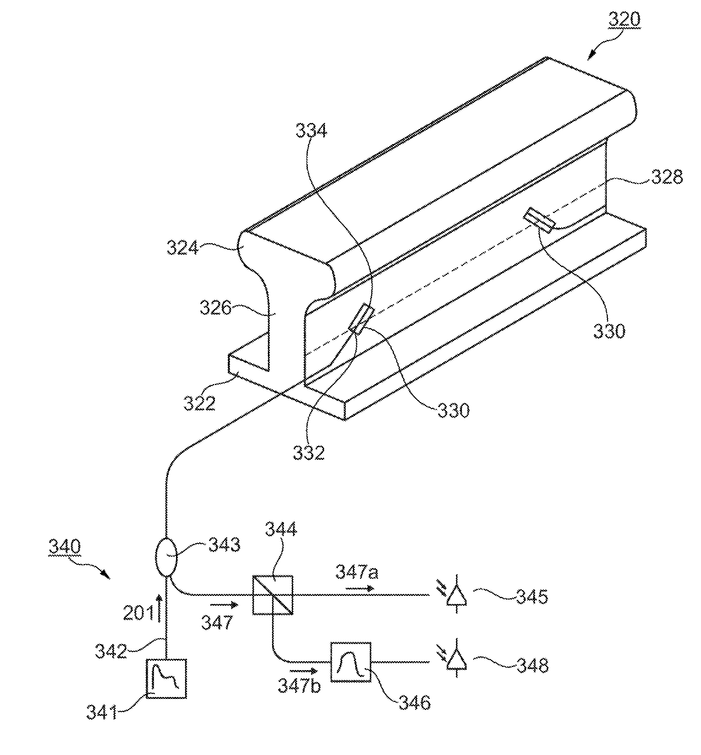
[0027]Embodiments of the present invention which are described herein relate inter alia to a use of at least one fiber-optic sensor unit for measuring a mechanical variable, a fiber-optic sensor unit for detecting a mechanical force acting on the rail, a rail measuring system and a method for mounting a fiber-optic sensor unit, in particular a fiber-optic sensor unit with a fiber Bragg grating, to a rail.

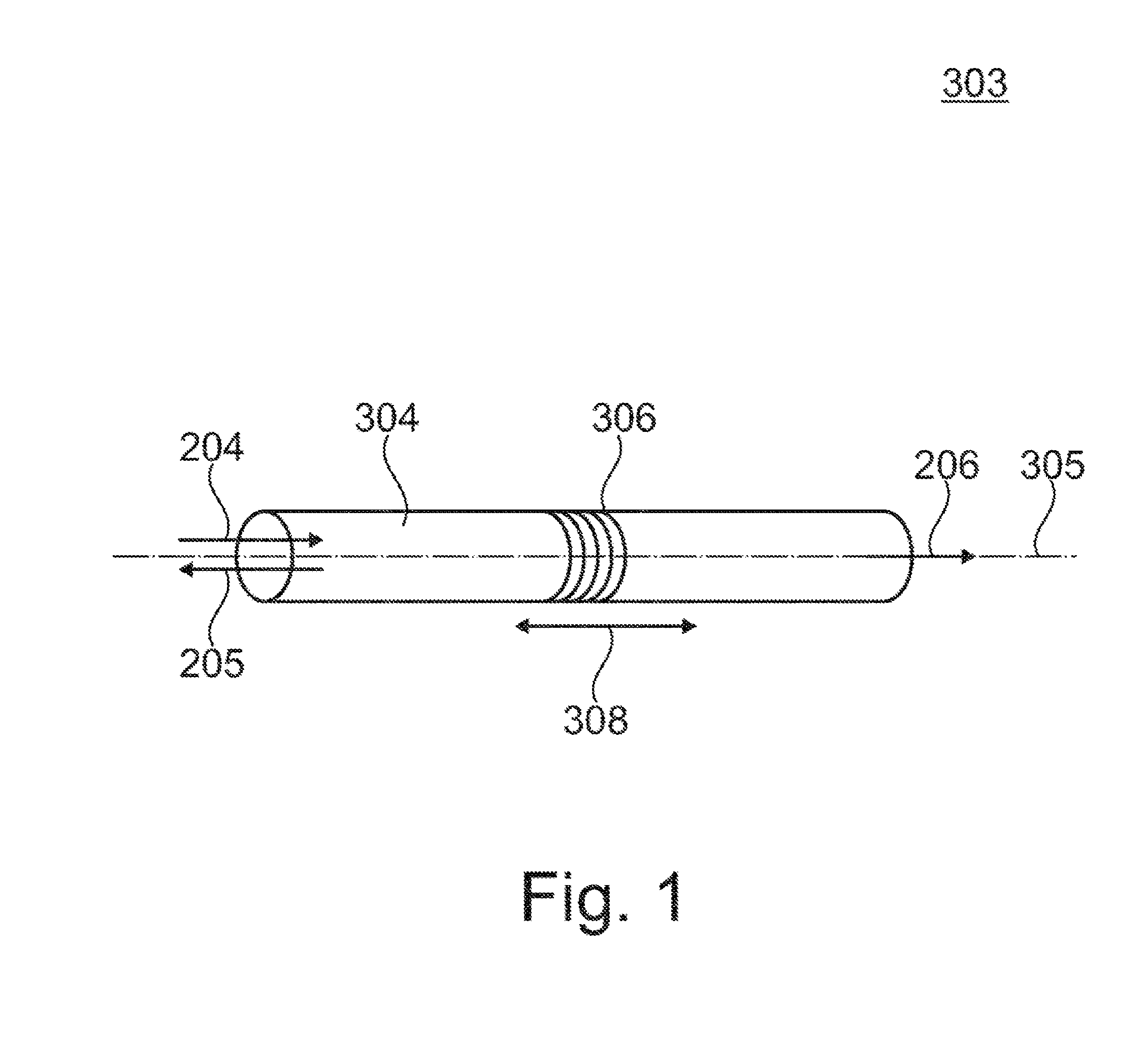
[0028]FIG. 1 illustrates a sensor or a sensor element 303 which is integrated in a fiber optic cable and comprises a fiber Bragg grating 306. Although FIG. 1 shows only one single fiber Bragg grating 306, it is clear that the present invention is not limited to data acquisition from one single fiber Bragg grating 306 but that a plurality of fiber Bragg gratings 306 can be arranged along a transmission fiber or a sensor fiber 304...


PUM

PropertyMeasurementUnit
angleaaaaaaaaaa
angleaaaaaaaaaa
angleaaaaaaaaaa

Abstract

At least one fiber-optic sensor unit measures a mechanical variable which affects a rail having a certain length and a neutral axis that extends along said length of the rail. The at least one fiber-optic sensor unit is disposed at an angle of 30° to 60°, in particular 45°, relative to the neutral axis or at an angle of −30° to −60°, in particular −45°, relative to the neutral axis. The at least one fiber-optic sensor unit is irradiated with primary light in order to generate a signaling light in a reflection mode or transmission mode. The intensity of the signaling light is sensed. The signaling light is evaluated.

Description

CROSS-REFERENCE TO RELATED APPLICATIONS[0001]This continuation application claims priority to PCT / EP2015 / 050797 filed on Jan. 16, 2015 which has published as WO 2015 / 110361 A2 and also the German application number 10 2014 100 653.4 filed on Jan. 21, 2014, the entire contents of which are fully incorporated herein with these references.DESCRIPTIONField of the Invention[0002]The present invention relates in general to an optical measuring device for detecting measured variables by means of sensors that are embedded in optical fibers, and relates, in particular, to a use of at least one fiber-optic sensor element for measuring a mechanical variable that acts on a rail, and to a rail measuring system. The present invention moreover relates to a method of mounting a fiber-optic sensor element to a rail.Background of the Invention[0003]Fiber-optic sensors are becoming more and more important in measuring systems. In this connection, one or more sensors that are embedded in fiber optic ca...

Claims


Application Information

Patent Timeline
Patent Type & Authority Applications(United States)
IPC IPC(8): G01L1/24B61L23/04B61L25/02G01M11/08
CPCG01L1/246B61L25/021B61L23/04G01M11/085B61K9/08B61L23/042B61L23/047G01L1/247G01M11/08
Inventor GLUECK, MARTINMUELLER, MATHIAS
Owner THALES MANAGEMENT & SERVICES DEUT GMBH
Why Eureka
Try Eureka