Super-resolution microscopy methods and systems enhanced by dielectric microspheres or microcylinders used in combination with metallic nanostructures

a dielectric microsphere and metallic nanotechnology, applied in the field of super-resolution microscopy methods and systems, can solve the problems of diffraction-limited resolution, poor optical contrast, and label-free microscopy is more difficult than fluorescent microscopy, and achieve enhanced plasmonic near-field, improved optical contrast and resolution of ultra-small objects, and improved optical contrast and resolution.

Active Publication Date: 2016-12-08
THE UNITED STATES OF AMERICA AS REPRESETNED BY THE SEC OF THE AIR FORCE
View PDF7 Cites 11 Cited by
  • Summary
  • Abstract
  • Description
  • Claims
  • Application Information

AI Technical Summary

Benefits of technology

[0016]Another possibility offered by the methods and systems proposed in this patent is based on structured illumination of the object which can additionally increase the resolution. The spatial configuration of the coupled nanoplasmonic modes excited in such arrays is strongly dependent on the illumination wavelength. By changing the illumination wavelength, various illumination patterns can be realized. The corresponding images can be combined and processed collectively to increase the resolution of the images. The advantage provided by the structured illumination is well known. In this invention, we propose to use this advantage specifically in the case of microsphere-assisted imaging of objects illuminated by nanoplasmonic arrays. In this case, all advantages (near-field illumination, magnification involving near-fields and structured illumination), take place simultaneously that can result in further increase of the resolution.

Problems solved by technology

The label-free microscopy is more challenging compared to fluorescent microscopy because of the poor optical contrast of images of objects with subwavelength dimensions.
Since such image is observed by the microscope objective in the far-field, it has a diffraction-limited resolution.
However, due to the magnification of the system which takes place for extremely small object's features acquired with participation of its near-fields, the resulting resolution of the system can exceed the classical diffraction limit.

Method used


Image

  • Super-resolution microscopy methods and systems enhanced by dielectric microspheres or microcylinders used in combination with metallic nanostructures
  • Super-resolution microscopy methods and systems enhanced by dielectric microspheres or microcylinders used in combination with metallic nanostructures
  • Super-resolution microscopy methods and systems enhanced by dielectric microspheres or microcylinders used in combination with metallic nanostructures

Examples


first embodiment

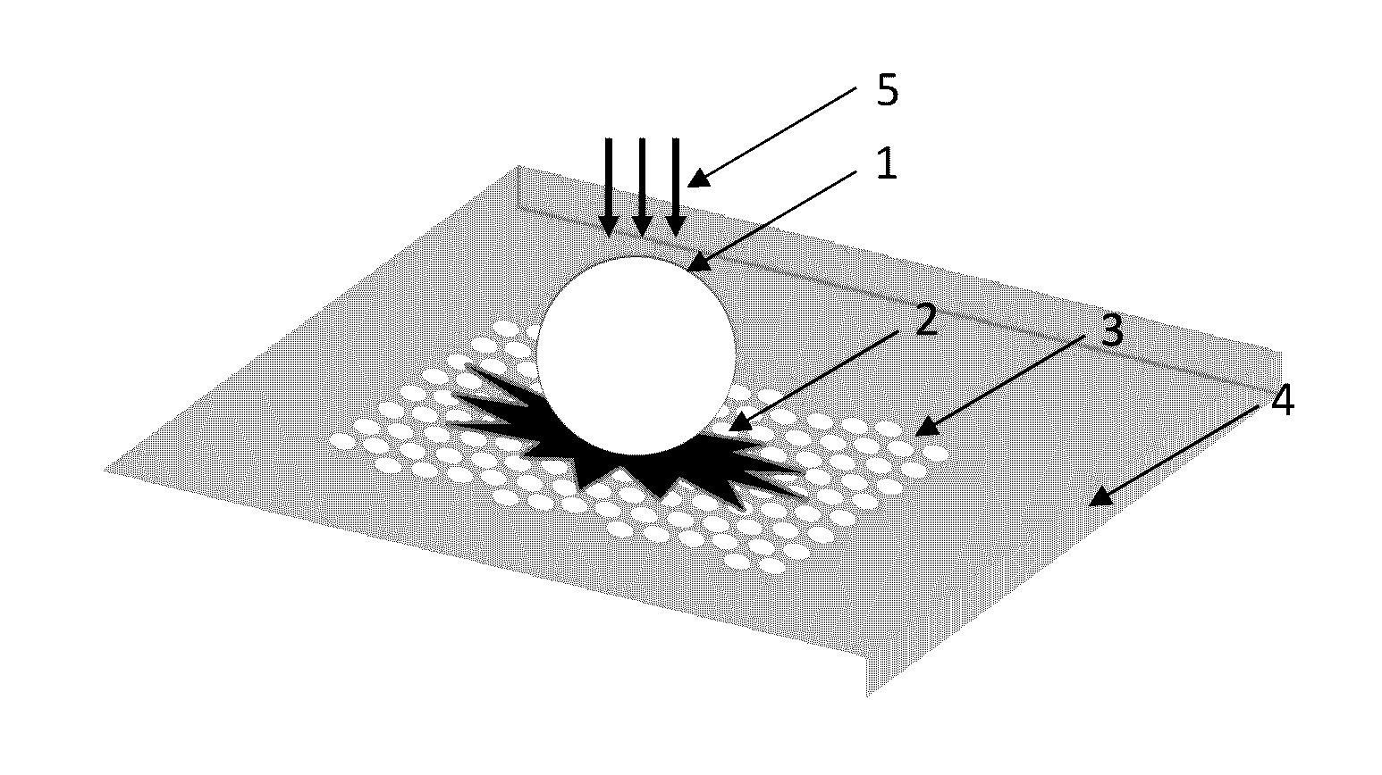
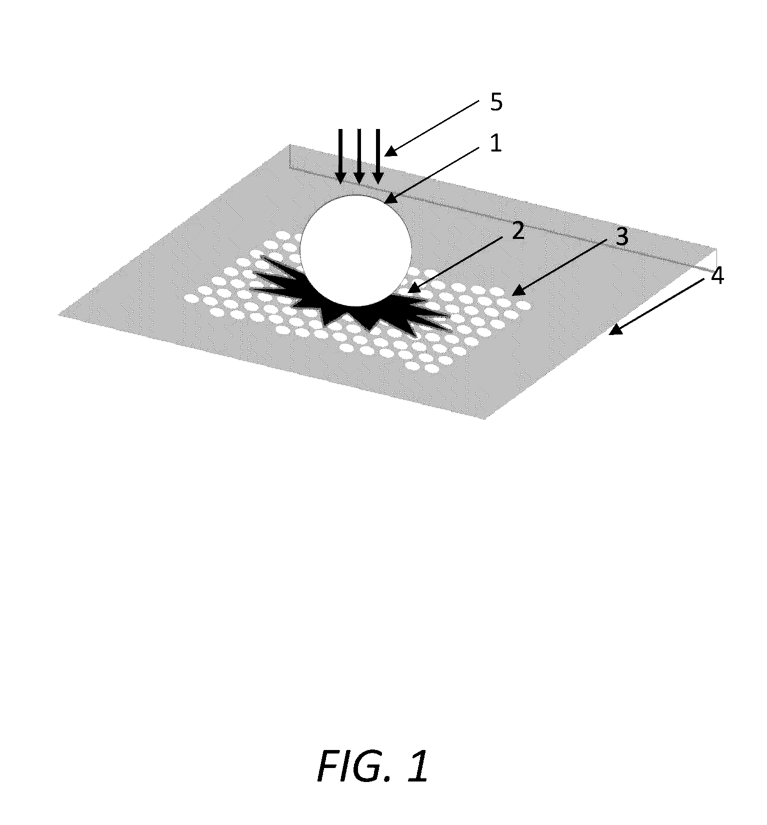
[0030]the proposed methods and systems is illustrated in FIG. 1. In order to project the image in the far-field we propose to use a previously developed technology of imaging through the microspheres or cylinders. (Only the case of a micro sphere is illustrated in FIG. 1). The proposed technology is expected to work for objects with the thickness limited by the wavelength of light. The microsphere or microcylinder the relatively small index of refraction (ns˜1.4-1.6) is placed above the object, so that its surface is located in near-field vicinity to the metallic nanostructure fabricated on the surface of the substrate. The object can be in a dry form or it can contain some amount of liquid, however the spheres or cylinders are not totally covered with liquid. Many biomedical and nanotechnology objects can be accommodated between the metallic nanostructure and the surface of microspheres or microcylinders. The examples include cells, viruses, proteins, carbon nanotubes, clusters of ...

second embodiment

[0032]the proposed methods and systems is illustrated in FIG. 3. It provides an additional enhancement of the resolution and quality of imaging due to use of liquid-immersed high-index (ns>1.8) microspheres or microcylinders. (Only the case of microspheres is illustrated in FIG. 3). They are totally submersed in a liquid. The height of the liquid is not critically important for the super-resolution imaging. It is particularly suitable for imaging biomedical structures since they are often water-immersed.

third embodiment

[0033]the proposed methods and systems is illustrated in FIG. 4. It provides an additional flexibility due to large number of microspheres or microcylinders with different diameters and, potentially, made from different materials, which are embedded in transparent flexible elastomeric slabs. (Only the case of microspheres is illustrated in FIG. 4). The spheres are held in nanometer-scale proximity to the bottom surface of the slabs or “coverslips”, Once the coverslip is attached to a nanoplasmonic structure, the tips of microspheres can experience the object near-fields leading to the possibility of super-resolution imaging. Each sphere has a field-of-view on the order of a quarter of its diameter. Multiple spheres allow inspecting larger area of the sample. Most importantly, the entire films can be controllably shifted along the sample providing the surface scanning functionality.


PUM

PropertyMeasurementUnit
diametersaaaaaaaaaa
plasmonic wavelengthaaaaaaaaaa

Abstract

Methods and systems for the super-resolution imaging can make visible strongly subwavelength feature sizes (even below 100 nm) in the optical images of biomedical or any nanoscale structures. The main application of the proposed methods and systems is related to label-free imaging where biological or other objects are not stained with fluorescent dye molecules or with fluorophores. This label-free microscopy is more challenging as compared to fluorescent microscopy because of the poor optical contrast of images of objects with subwavelength dimensions. However, these methods and systems are also applicable to fluorescent imaging. Their use is extremely simple, and it is based on application of the microspheres or microcylinders or, alternatively, elastomeric slabs with embedded microspheres or microcylinders to the objects which are deposited on the surfaces covered with thin metallic layers or metallic nanostructures. The mechanism of imaging involved use of the plasmonic near-fields for illuminating the objects and virtual imaging of these objects through microspheres or microcylinders. These methods and systems do not require use of fragile probe tips and slow point-by-point scanning techniques. These methods and systems can be used in conjunction with any types of microscopes including upright, inverted, fluorescence, confocal, phase-contrast, total internal reflection and others. Scanning the samples can be performed using micromanipulation with individual spheres or cylinders or using translation of the slabs. These methods and systems are applicable to dry, wet and totally liquid-immersed samples and structures.

Description

CROSS-REFERENCE[0001]The present patent application / patent claims the benefit of priority of co-pending U.S. Provisional Patent Application No. 62 / 171,438, filed on Jun. 5, 2015, and entitled “SUPER-RESOLUTION MICROSCOPY METHODS AND SYSTEMS ENHANCED BY DIELECTRIC MICROSPHERES AND METALLIC NANOSTRUCTURES,” the contents of which are incorporated in full by reference herein.STATEMENT OF GOVERNMENT INTEREST[0002]The United States Government has rights in the present invention pursuant to an employer-employee relationship with some of the inventors as U.S. Air Force Research Laboratory employees or contractors.FIELD[0003]The present invention relates generally to microscopy methods and systems. More specifically, the present invention relates to super-resolution microscopy methods and systems enhanced by dielectric microspheres or microcylinders used in combination with metallic nanostructures.BACKGROUND[0004]Super-resolution is introduced in respect to conventional diffraction-limited r...

Claims


Application Information

Patent Timeline
Patent Type & Authority Applications(United States)
IPC IPC(8): G02B27/58G02B21/32G02B5/00H04N5/225G01N21/17
CPCG02B27/58H04N5/2254G01N21/17G01N2021/1746G02B21/32G01N2021/1782G02B5/008B82Y30/00B82Y35/00G01N21/01
Inventor ASTRATOV, VASILY N.LIMBEROPOULOS, NICHOLAOS I.URBAS, AUGUSTINE M.
Owner THE UNITED STATES OF AMERICA AS REPRESETNED BY THE SEC OF THE AIR FORCE
Why Eureka
Try Eureka