
Terminal, connection structural body, and method of manufacturing terminal

Inactive Publication Date: 2016-12-08
FURUKAWA ELECTRIC CO LTD +1
View PDF5 Cites 6 Cited by
  • Summary
  • Abstract
  • Description
  • Claims
  • Application Information

AI Technical Summary

Benefits of technology

The invention covers the entire cut end surface of a metal member with a resin-covered part, resulting in a barrier to corrosion current flow between the exposed part of the conductor and the terminal. This prevents galvanic corrosion and ensures a long-lasting, reliable connection between the conductor and terminal.

Problems solved by technology

However, in a connection structural body with an electrical wire using an open-barrel type terminal, when water or the like adheres to a connection portion (contact point) between an electrical wire and a terminal, oxidation on a metal surface used for an electrical wire and a terminal base material progresses, resulting in an increase in electric resistance in the connection portion.
Further, when an electrical wire and a terminal use a different metal, corrosion between different types of metal progresses.
Progression of oxidation or corrosion of metal in the connection portion results in a breakage or a connection failure in the connection portion, which possibly affects a product longevity.
In particular, in recent years, a wire harness is put to practical use where an aluminum alloy is used as an electrical wire and a copper alloy is used as a terminal base material, so that a problem of oxidation and corrosion in a connection portion becomes significant.

Method used


Image

  • Terminal, connection structural body, and method of manufacturing terminal
  • Terminal, connection structural body, and method of manufacturing terminal
  • Terminal, connection structural body, and method of manufacturing terminal

Examples


first embodiment

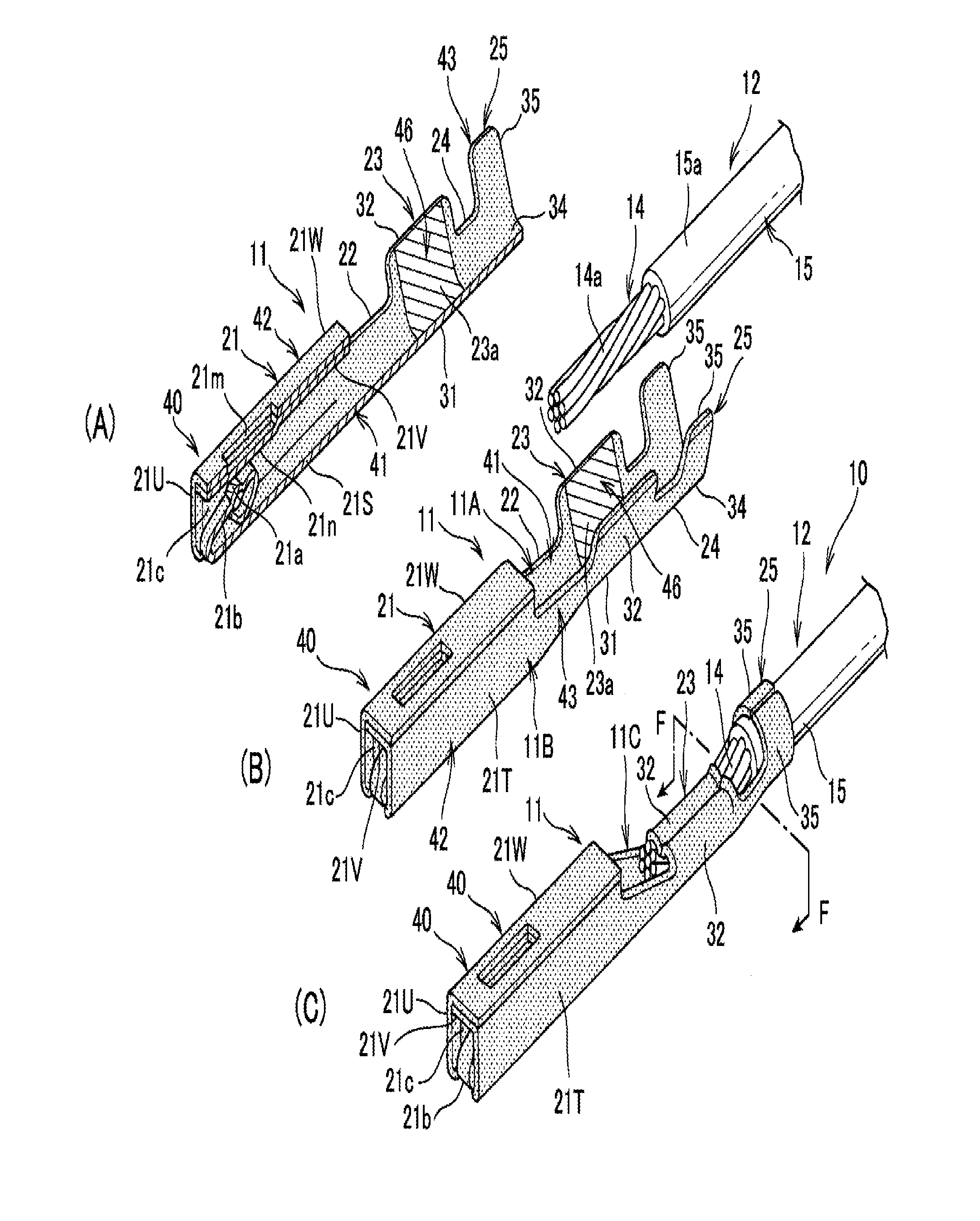
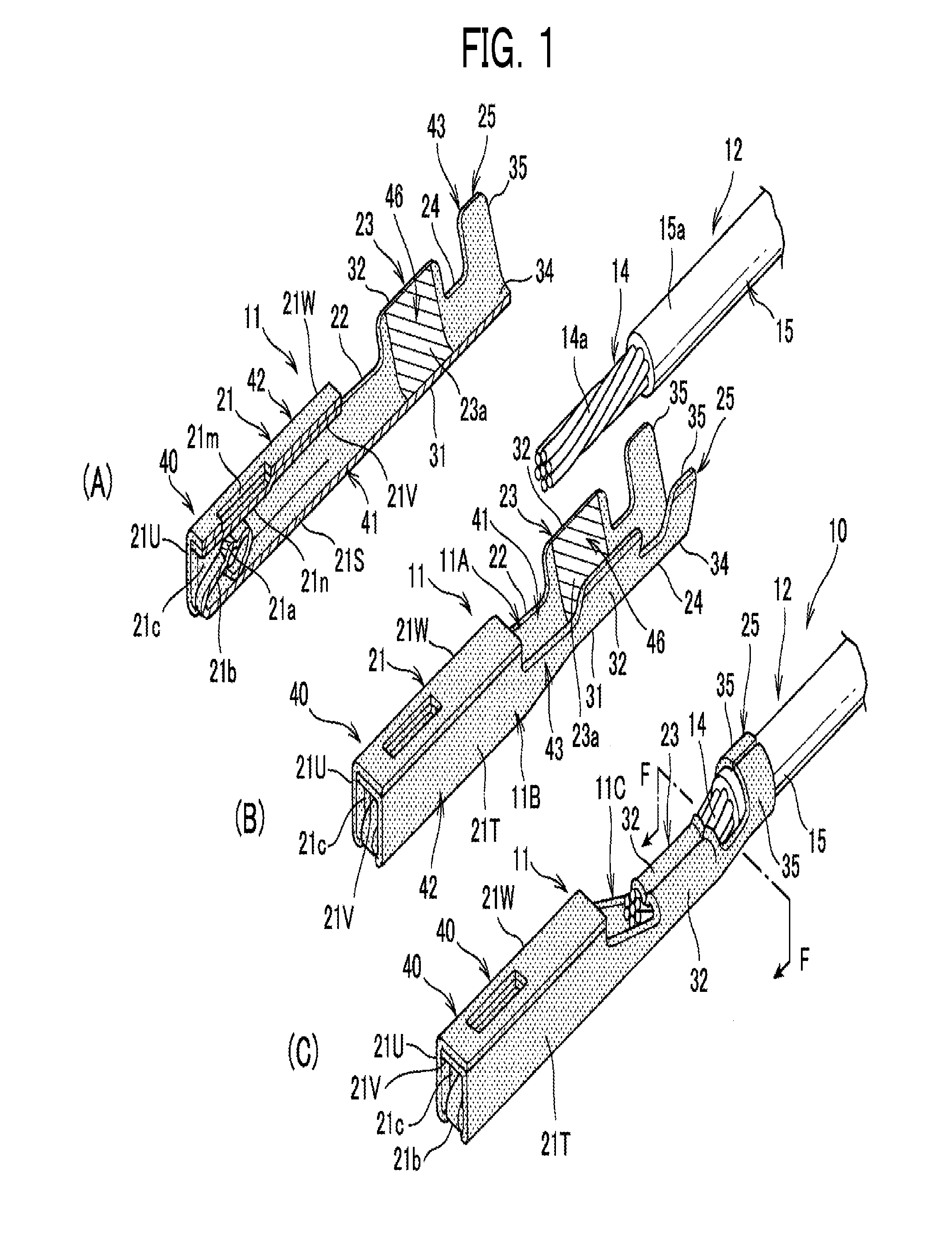
[0032]FIG. 1 is a perspective view showing a terminal 11 and a covered electrical wire 12 that configure a connection structural body 10 of a first embodiment of the present invention. FIG. 1(A) is a perspective view showing the terminal 11 that is cut off at a widthwise center before crimping the covered electrical wire, FIG. 1(B) is a perspective view showing the terminal 11 and the covered electrical wire 12 before crimping the wire, and FIG. 1(C) is a perspective view showing the connection structural body 10.

[0033]As shown in FIG. 1(A) and FIG. 1(B), the terminal 11 is, for example, a female terminal, and integrally includes a box part 21, a first transition part 22, a wire barrel part 23, a second transition part 24, and an insulation barrel part 25 in the order from one end side of a longitudinal direction.

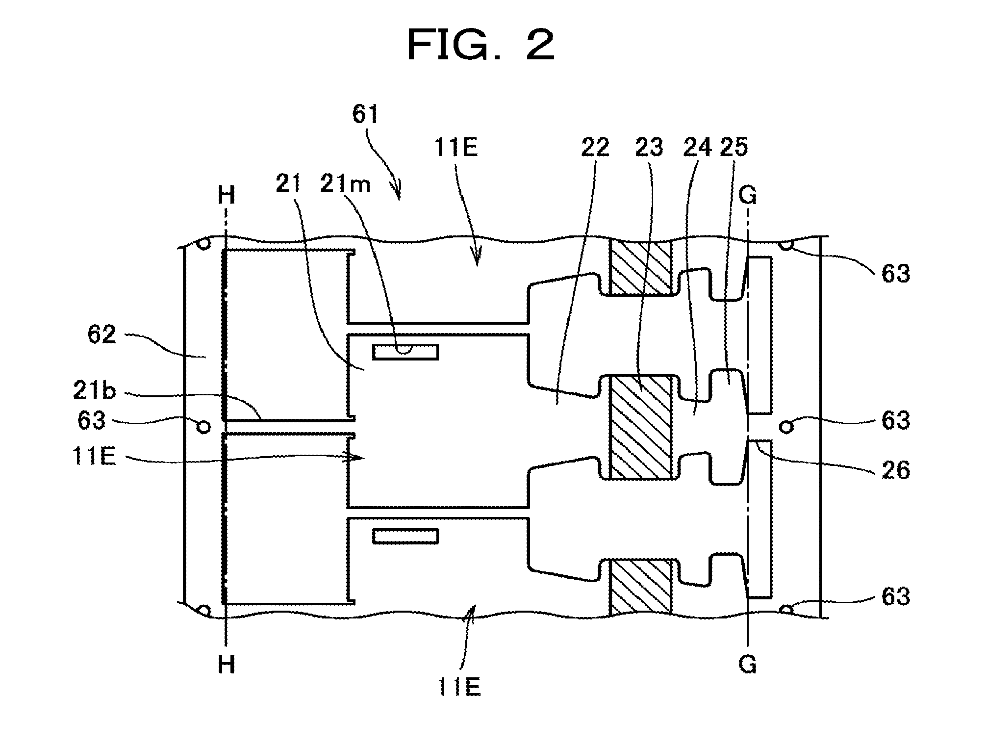
[0034]The terminal 11 is formed by blanking a metal member and applying to bend processing (press processing).

[0035]A metal member consists of a base material of a metal ma...

second embodiment

[0094]FIG. 6 is a perspective view showing the male terminal 81 of the second embodiment of the present invention.

[0095]The male terminal (terminal) 81 has a box part 83, a plate-shaped tab 84 protruding from one end of the box part 83, a tube-shaped swaging part 85, and a transition part 86 serving as a bridge for the box part 83 and the tube-shaped swaging part 85, and a base material is made of copper or a copper alloy.

[0096]The box part 83 is a portion that regulates an insertion position when the tab 84 is inserted into the box part 21 (see FIG. 1) of the male-type terminal 11 (see FIG. 1) as well as a portion that is gripped by fingers.

[0097]The tab 84 has a rectangular flat plate part 84a and a pointed taper part 84b formed at a tip part of the flat plate part 84a.

[0098]The contact projecting part 21a (see FIG. 1(A)) of the terminal contacts a first contact surface 84c that is one side of the flat plate part 84a, and the lower projecting part 21n (see FIG. 1(A)) of the box p...


PUM


Abstract

A terminal and connection structural body that can restrain galvanic corrosion occurring between a core wire of a covered electrical wire and a terminal formed of different types of metal, and that can ensure conductive function. The terminal includes a box part as a connection part connected to another terminal and a wire barrel part as a crimping part crimp-connected to a covered electrical wire. All of a non-contact part, including an end surface as a cut surface upon blanking a metal member, is covered with a resin covered part, where the non-contact part is other than a contact part with another terminal, a non-covered part, and a contact part with an end part as an exposed part of a core wire of a covered electrical wire, a non-covered part.

Description

TECHNICAL FIELD[0001]The present invention relates to a terminal used, for example, for a wire harness for an automobile, a connection structural body thereof, and a method of manufacturing a terminal.BACKGROUND ART[0002]When a covered electrical wire and a terminal in a wire harness for an automobile or the like are connected, a crimp-connection is generally used in which an electrical wire is crimped and swaged by a so-called open-barrel type terminal. However, in a connection structural body with an electrical wire using an open-barrel type terminal, when water or the like adheres to a connection portion (contact point) between an electrical wire and a terminal, oxidation on a metal surface used for an electrical wire and a terminal base material progresses, resulting in an increase in electric resistance in the connection portion. Further, when an electrical wire and a terminal use a different metal, corrosion between different types of metal progresses. Progression of oxidation...

Claims


Application Information

Patent Timeline
IPC IPC(8): H01R4/62H01R13/03H01R43/20H01R13/11H01R43/04H01R4/18H01R13/04
CPCH01R4/62H01R4/185H01R13/035H01R13/04H01R2201/26H01R4/18H01R43/04H01R43/20H01R13/113
Inventor TACHIBANA, AKIRA
Owner FURUKAWA ELECTRIC CO LTD
Learn More