Optical-power monitoring device, fiber laser, and optical-power monitoring method

a monitoring device and optical fiber technology, applied in the direction of optical radiation measurement, photometry using electric radiation detectors, instruments, etc., can solve the problems of unstable oscillation state of outputted light, decrease in power of excitation light, and decrease in power of light outputted from a fiber laser, so as to accurately measure the power of light propagating through an optical fiber

Active Publication Date: 2016-12-08
THE FUJIKURA CABLE WORKS LTD
View PDF1 Cites 7 Cited by
  • Summary
  • Abstract
  • Description
  • Claims
  • Application Information

AI Technical Summary

Benefits of technology

[0016]According to the above configuration, it is possible to accurately measure power of light propagating through an optical fiber.

Problems solved by technology

Here, a decrease in power of excitation light, an increase in loss occurring in an optical fiber, or the like may cause a decrease in power of light outputted from a fiber laser.
This may cause an oscillation state of outputted light to be unstable, and may accordingly cause a variation in power of the outputted light.
Therefore, in any of the above cases, since power of outputted light varies from original power, a processing characteristic is deteriorated.

Method used


Image

  • Optical-power monitoring device, fiber laser, and optical-power monitoring method
  • Optical-power monitoring device, fiber laser, and optical-power monitoring method
  • Optical-power monitoring device, fiber laser, and optical-power monitoring method

Examples


Embodiment Construction

[0028]The following description will discuss an embodiment of the present invention with reference to the drawings. In the present embodiment, an example will be described in which a light power monitoring device is applied to optical fibers constituting a fiber laser.

[0029][Light Power Monitoring Device]

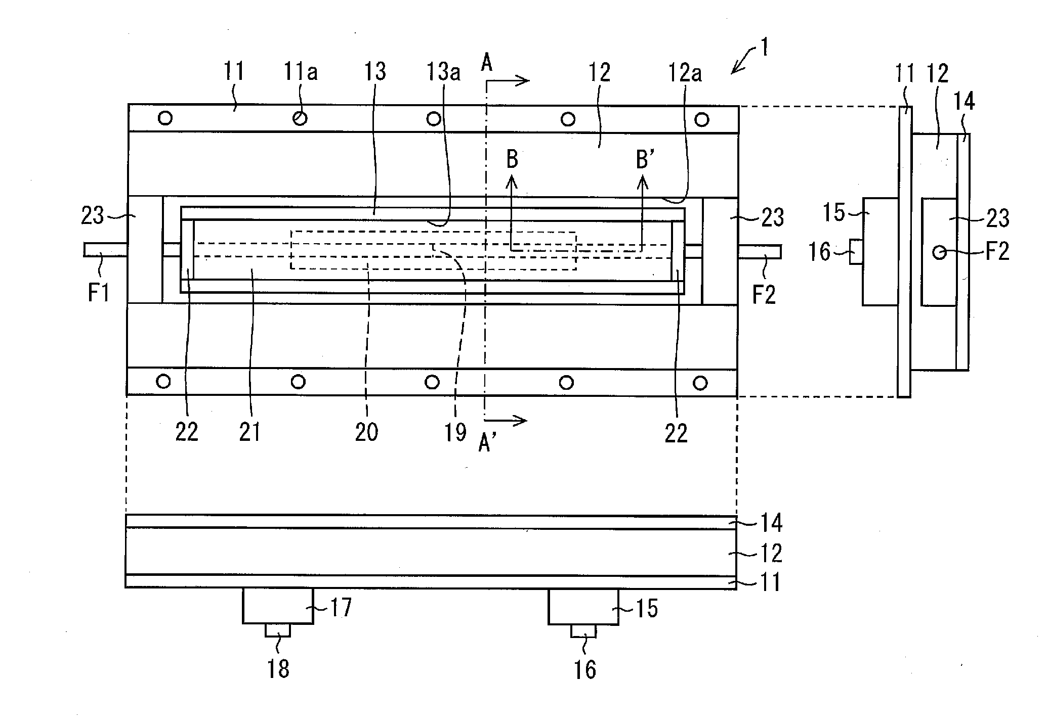
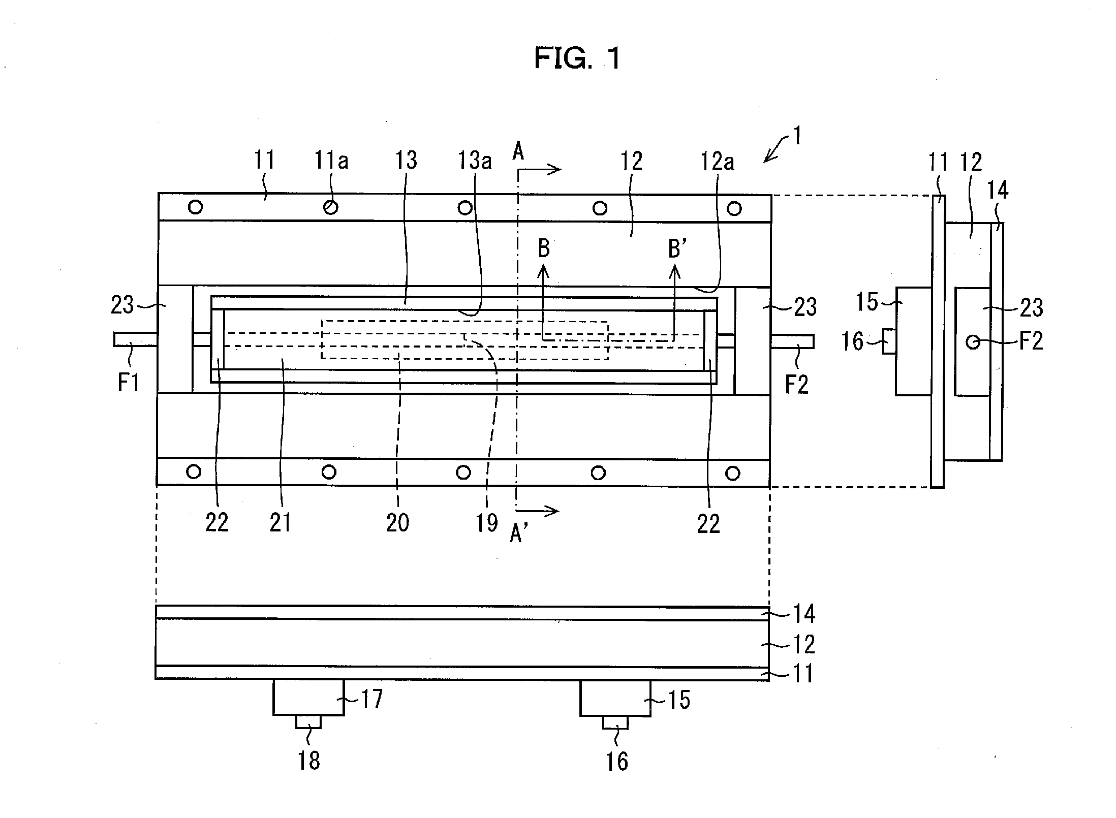
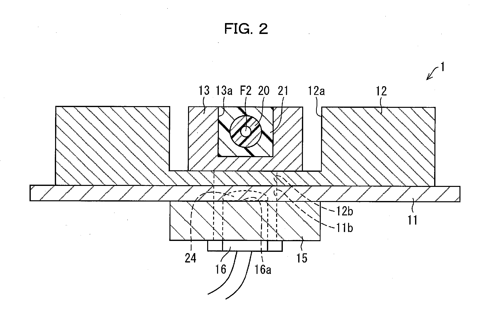
[0030]FIG. 1 is a three-side view illustrating a configuration of a light power monitoring device 1 in accordance with the present embodiment (upper left: a top view, upper right: an anterior side view (right side view), lower left: front view). FIG. 2 is a cross-sectional view illustrating the light power monitoring device 1, taken along a line A-A′ illustrated in FIG. 1.

[0031]The light power monitoring device 1 measures power of light leaking from a side surface (outer peripheral surface) of each of optical fibers F1 and F2 (first and second optical fibers). The light power monitoring device 1 includes a base 11, a grooved plate 12, a reinforced member 13, a cover plate 14, a fixi...


PUM


Abstract

The light power monitoring device includes: a first optical fiber; a second optical fiber connected to the first optical fiber; a low-refractive-index resin layer which covers (i) a connection between the first and the second optical fibers and (ii) a predetermined region of the second optical fiber which region extends from the connection toward a forward-propagating-light-output side; a high-refractive-index resin layer which covers a region of the second optical fiber which region is not covered by the low-refractive-index resin layer; and an outputted light detecting device which is provided at a position corresponding to an end of the low-refractive-index resin layer which end is located on the forward-propagating-light-output side of the second optical fiber or at a position which is away toward the forward-propagating-light-output side of the second optical fiber from the position corresponding to the end of the low-refractive-index resin layer.

Description

[0001]This application is a Continuation of PCT International Application No. PCT / JP2014 / 079989 filed in Japan on Nov. 12, 2014, which claims the benefit of Patent Application No. 2014-033337 filed in Japan on Feb. 24, 2014, the entire contents of which are hereby incorporated by reference.TECHNICAL FIELD[0002]The present invention relates to (i) a light power monitoring device which measures power of light leaking from an optical fiber and (ii) a light power monitoring method for measuring power of light leaking from an optical fiber. Moreover, the present invention relates to a fiber laser including such a light power monitoring device.BACKGROUND ART[0003]In the field of laser processing, more and more fiber lasers have been used according to a recent increase in their power.[0004]Here, a decrease in power of excitation light, an increase in loss occurring in an optical fiber, or the like may cause a decrease in power of light outputted from a fiber laser. Furthermore, while an ob...

Claims


Application Information

Patent Timeline
Patent Type & Authority Applications(United States)
IPC IPC(8): H01S3/00H01S3/067G02B6/26G02B6/42G01J1/42
CPCH01S3/0014G02B6/4287H01S3/06704G02B6/4286G02B6/264G01J1/4257G01J1/0295G01J1/0425G02B6/4291H01S3/0675H01S3/094007
Inventor KASHIWAGI, MASAHIRO
Owner THE FUJIKURA CABLE WORKS LTD
Why Eureka
Try Eureka