Current Transformer Core, Current Transformer And Power Meter

a current transformer and transformer core technology, applied in the direction of transformer/inductance cores, conductors, magnetic bodies, etc., can solve the problems of poor linearity of the magnetization loop, large tension, and difficulty in providing high-accuracy current transformers, etc., to achieve accurate measurement of power

Active Publication Date: 2008-06-05
HITACHI METALS LTD
View PDF7 Cites 16 Cited by
  • Summary
  • Abstract
  • Description
  • Claims
  • Application Information

AI Technical Summary

Benefits of technology

[0015]Accordingly, an object of the present invention is to provide a current transformer core capable of accurately measuring the power of unsymmetrical-waveform current and distorted waveform current.

Problems solved by technology

Particularly when a low-permeability material is used for the magnetic core, this tendency is large.
A ratio error is a relative error of the measured value to the ideal value at each measurement point, indicating how the measured current is accurate.
Because inexpensive, high-magnetic-flux-density silicon steel sheets have low permeability, large hysteresis, and poor magnetization loop linearity, they suffer largely varying ratio error and phase difference, resulting in difficulty in providing high-accuracy current transformers.
Further, having a large residual magnetic flux density, they cannot easily conduct the accurate measurement of unsymmetrical current such as half-wave, sinusoidal, current, etc.
The Fe-based amorphous alloys suffer large variations of a ratio error and a phase difference when used for the current transformer.
However, the saturation magnetic flux densities of the Co-based, amorphous alloys are insufficiently as low as 1.2 T or less, and they are thermally unstable.
Thus, there are problems as follows: the measurement is limited when biased with large current; they are not necessarily sufficient in size reduction and stability; and because their permeability cannot be increased so high from the aspect of magnetic saturation in view of direct current superposition, they have large ratio error and phase difference, important characteristics for current transformers.
In addition, the Co-based, amorphous alloys are disadvantageous in cost because they contain a large amount of expensive Co.
Such high-permeability materials can measure the power of positive-negative-symmetrical current and voltage waveform, but cannot measure the power of unsymmetrical-waveform current and distorted-waveform current accurately.
The cores of the Fe-based, nano-crystalline, soft-magnetic alloys having high saturation magnetic flux density and permeability are suitable for current transformers such as leakage circuit breakers, etc., but they have so small HK that they cannot easily measure current in the case of direct current bias because of their magnetic saturation.
Thus, they are not suitable for the measurement of such unsymmetrical-waveform current.
Necessary to meet such demand is a current transformer core made of a magnetic material having a low residual magnetic flux density, small hysteresis, and good magnetization curve linearity, which is not easily saturable and generates a relatively large anisotropic magnetic field HK.

Method used


Image

  • Current Transformer Core, Current Transformer And Power Meter
  • Current Transformer Core, Current Transformer And Power Meter
  • Current Transformer Core, Current Transformer And Power Meter

Examples


example 1

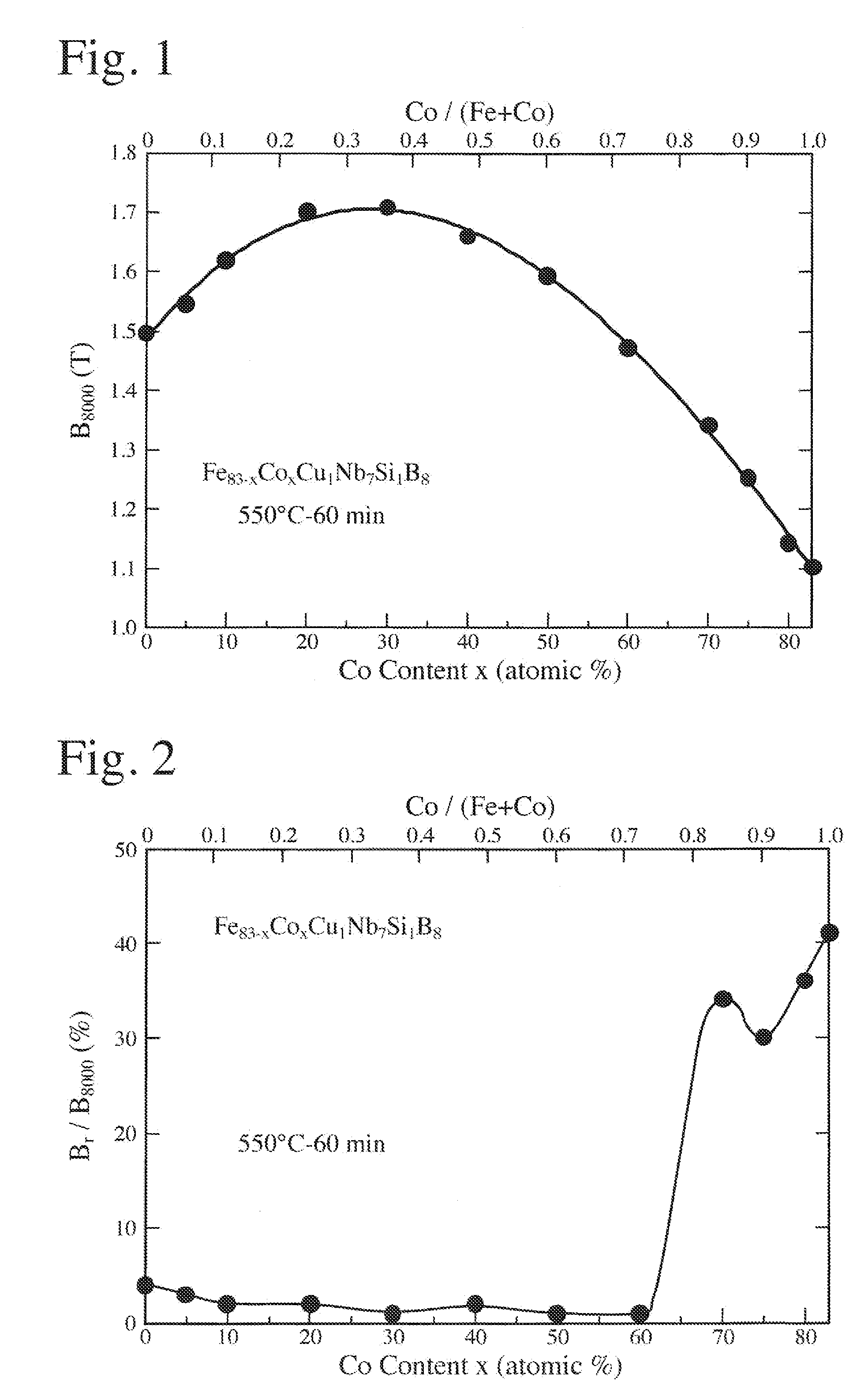
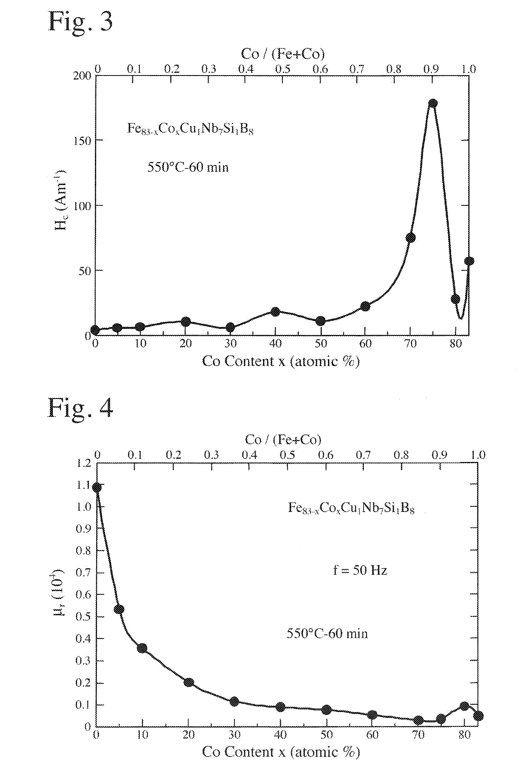
[0070]An alloy melt of Fe83-xCoxCuxNb7Si1B8 (by atomic %) was rapidly quenched by a single roll method, to obtain a thin amorphous alloy ribbon of 5 mm in width and 21 μm in thickness. This thin amorphous alloy ribbon was wound to a toroidal core having an outer diameter of 30 mm and an inner diameter of 21 mm. The magnetic core was placed in a heat treatment furnace filled with a nitrogen gas, to carry out a heat treatment while applying a magnetic field of 280 k Am−1 in a direction perpendicular to the magnetic circuit of the magnetic core (in the width direction of the thin alloy ribbon, or in the height direction of the magnetic core). A heat treatment pattern used comprised temperature elevation at 10° C. / minute, keeping at 550° C. for 1 hour, and cooling at 2° C. / minute. Observation by an electron microscope revealed that the heat-treated alloy had a structure, about 70% of which was occupied by crystal grains having a particle size of about 10 nm and a body-cubic crystal stru...

example 2

[0074]Alloy melts having the compositions shown in Table 2 were rapidly quenched by a single roll method in an Ar atmosphere, to obtain thin amorphous alloy ribbons of 5 mm in width and 21 μm in thickness. Each thin amorphous alloy ribbon was wound to a current transformer core having an outer diameter of 30 mm and an inner diameter of 21 mm. Each magnetic core was heat-treated in the same manner as in Example 1, and then subjected to magnetic measurement. In the heat-treated alloy structure, ultrafine crystal grains having a particle size of 50 nm or less were generated. No. 33 represents a magnetic core made of an Fe-based, nano-crystalline alloy (Comparative Example), No. 34 represents a magnetic core made of a Co-based, amorphous alloy (Comparative Example), and No. 35 represents a magnetic core made of Parmalloy (Comparative Example).

[0075]With respect to a current transformer produced by using each magnetic core, phase difference and ratio error of rated current (expressed by ...

example 3

[0079]An alloy melt of Fe53.8 Co25Cu0.7Nb2.6Si9B9 (by atomic %) was rapidly quenched by a single roll method to obtain a thin amorphous alloy ribbon of 5 mm in width and 21 μm in thickness. This thin amorphous alloy ribbon was wound to a toroidal core having an outer diameter of 30 mm and an inner diameter of 21 mm. The magnetic core was placed in a heat treatment furnace having a nitrogen gas atmosphere, and heat-treated in the same manner as in Example 1, except that the heat treatment pattern comprised temperature elevation at 5° C. / minute, keeping at 530° C. for 2 hours, and cooling at 1° C. / minute. Observation by an electron microscope revealed that the heat-treated alloy had a structure, about 72% of which was occupied by crystal grains having a particle size of about 10 nm and a body-cubic crystal structure, the balance being mainly an amorphous phase. An X-ray diffraction pattern indicated crystal peaks corresponding to the body-cubic crystal phase.

[0080]Measurement revealed...


PUM

PropertyMeasurementUnit
particle sizeaaaaaaaaaa
magnetic flux densityaaaaaaaaaa
temperatureaaaaaaaaaa

Abstract

A current transformer core made of an alloy having a composition represented by the general formula: Fe100-x-a-y-cMxCuaM′yX′c (by atomic %), wherein M is Co and/or Ni, M′ is at least one element selected from the group consisting of V, Ti, Zr, Nb, Mo, Hf, Ta and W, X′ is Si and/or B, and x, a, y and c are numbers satisfying 10≦x≦50, 0.1≦a≦3, 1≦y≦10, 2≦c≦30, and 7≦y+c≦31, respectively; at least part or all of the alloy structure being composed of crystal grains having an average particle size of 50 nm or less.

Description

FIELD OF THE INVENTION[0001]The present invention relates to a current transformer core suitable for detecting unsymmetrical-waveform alternating current such as half-wave, sinusoidal, alternating current, etc. and direct-current-superimposed alternating current, and a current transformer and a power meter using such core.BACKGROUND OF THE INVENTION[0002]Power meters used to detect the power consumption of electric appliances and facilities at homes and in industry are categorized into induction-type power meters and electronic power meters. Although induction-type power meters comprising rotating disks were conventionally predominant, the electronic power meters are recently finding wider use due to the development of electronics. Power meters adapted to conventional standards such as IEC62053-22, etc. cannot conduct the accurate detection of distorted-waveform current such as half-wave, sinusoidal, alternating current, etc., failing to measure power accurately. Accordingly, IEC620...

Claims


Application Information

Patent Timeline
Patent Type & Authority Applications(United States)
IPC IPC(8): H01F27/24H01F27/28H01B1/22
CPCC22C38/002H01F1/15333C22C38/02C22C38/10C22C38/105C22C38/12C22C38/14C22C38/16C22C45/02H01F1/14708H01F1/14766H01F1/15308H01F1/15316H01F38/30H01F41/0226C22C33/003C22C38/005
Inventor YOSHIZAWA, YOSHIHITONAOE, MASAMU
Owner HITACHI METALS LTD
Why Eureka
Try Eureka