Method and system for measuring interference signal in carrier signal

a carrier signal and interference signal technology, applied in the field of mobile communication, can solve the problems of carrier interference being considered as a zero-mean stochastic process, measurement errors exist in carrier interference measurement, carrier interference signal may not necessarily satisfy the assumption of zero mean value, etc., to achieve accurate measurement of total power

Active Publication Date: 2015-03-19
CHINA TELECOM CORP LTD
View PDF2 Cites 3 Cited by
  • Summary
  • Abstract
  • Description
  • Claims
  • Application Information

AI Technical Summary

Benefits of technology

[0006]It has been found by the applicant that some measurement errors exist in existing carrier interference signal measurement methods. One object of this disclosure is to provide a new technical solution capable of, taking non-zero mean value carrier interference signal into account, accurately measuring the total power of interference signal within a carrier signal.

Problems solved by technology

However, in existing carrier interference measurement methods, carrier interference is considered as a zero-mean stochastic process.
According to a research on existing carrier interference measurement methods of the applicant, it has been found that some measurement errors exist in those carrier interference measurement methods, because carrier interference is considered as a zero-mean stochastic process in existing carrier interference measurement methods.
However, in practical applications, due to adjacent cell interference and other reasons, carrier interference signal may not necessarily satisfy the assumption of having a zero mean value.
Thus, results obtained with existing carrier interference signal measurement methods are not accurate enough, and a study on a method for measuring non-zero mean value carrier interference signal is desirable.
It has been found by the applicant that some measurement errors exist in existing carrier interference signal measurement methods.

Method used


Image

  • Method and system for measuring interference signal in carrier signal
  • Method and system for measuring interference signal in carrier signal
  • Method and system for measuring interference signal in carrier signal

Examples


Embodiment Construction

[0041]Various exemplary embodiments of the present disclosure will now be described in detail with reference to the drawings. It should be noted that the relative arrangement of the components and steps, the numerical expressions, and numerical values set forth in these embodiments do not limit the scope of the present disclosure unless it is specifically stated otherwise.

[0042]Meanwhile, it should be appreciated that, for the convenience of description, various parts shown in those drawings are not necessarily drawn on scale.

[0043]The following description of at least one exemplary embodiment is merely illustrative in nature and is in no way intended to limit the disclosure, its application, or uses.

[0044]Techniques, methods and apparatus as known by one of ordinary skill in the relevant art may not be discussed in detail but are intended to be part of the specification where appropriate.

[0045]In all of the examples illustrated and discussed herein, any specific values should be in...


PUM


Abstract

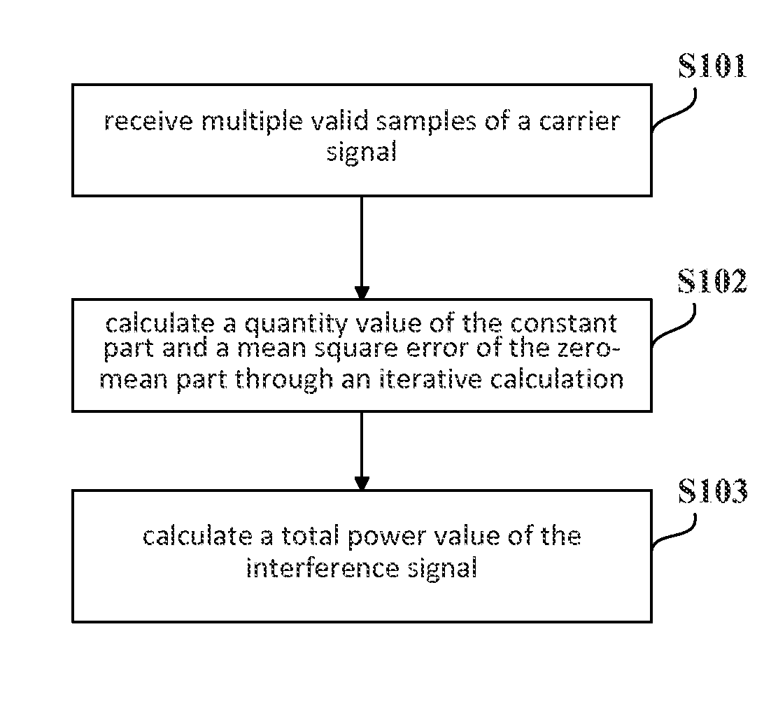
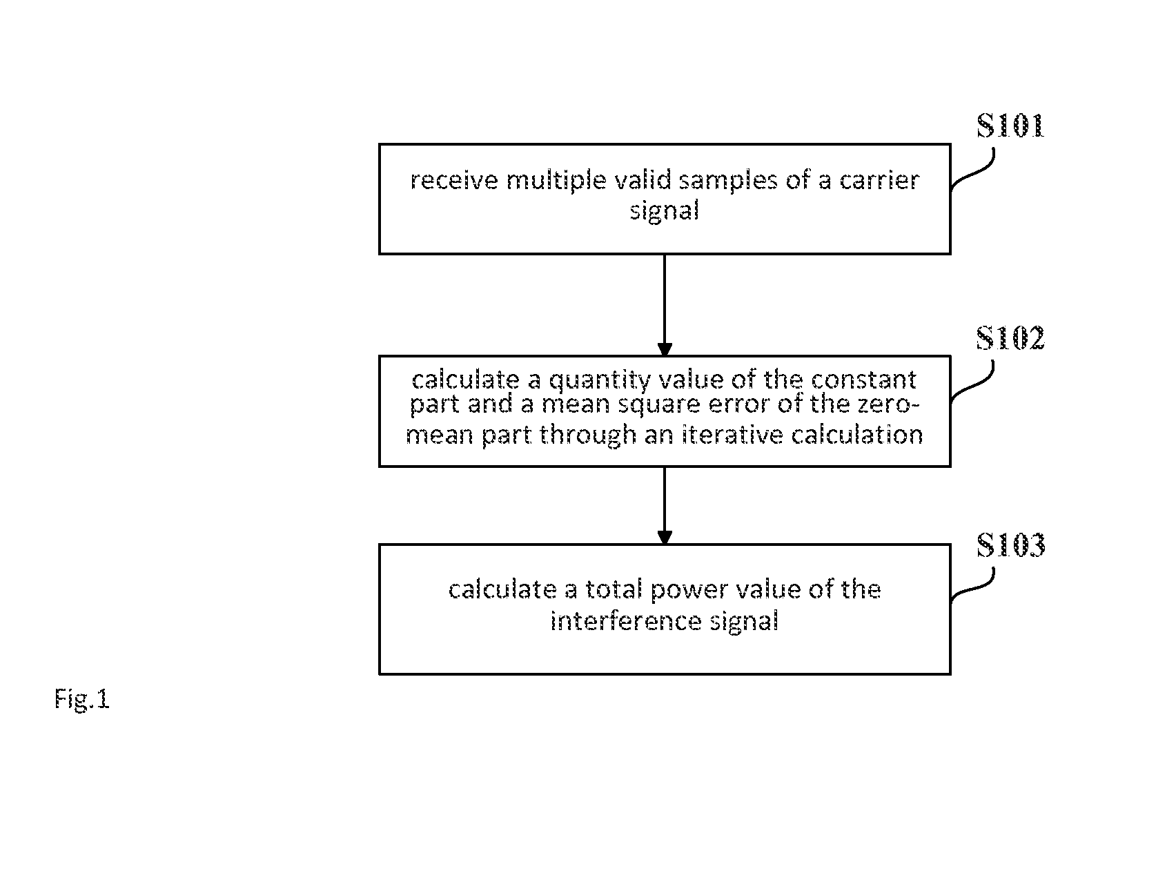
Disclosed in the present disclosure are a method and system for measuring interference signals in carrier signals. The method comprises: receiving multiple valid samples of the carrier signals; based on the multiple valid samples of the carrier signals, gaining value of constant part and mean square error of zero mean part in the interference signals through iterative calculation; calculating the total power value of the interference signals. Since considering the constant part in the interference signals, the measurement method is suitable in the case that the interference signals in the carrier signals is non-zero mean value, and the obtained measurement result of the interference signals will be more accurate than the result through the existing method.

Description

TECHNICAL FIELD[0001]This disclosure relates to the technical field of mobile communication, and more particularly to a method and system for measuring interference signal in a carrier signal.DESCRIPTION OF THE RELATED ART[0002]In multicarrier systems, a data stream is generally split into multiple sub bit streams, each sub data stream having a low bit rate, and a corresponding subcarrier is modulated with low-rate multiple-state symbols so as to realize the parallel transmission of multiple symbol streams at a low rate. A representative modulation method in multicarrier systems is Orthogonal Frequency Division Multiplexing (OFDM), in which subcarriers are uniformly distributed over a frequency band and are orthogonal to each other. Being a candidate technique for 4G mobile communication systems in the physical layer, subcarriers may overlap with each other to improve spectrum utilization.[0003]In actual systems, modulation and demodulation may be realized with Inverse Discrete Four...

Claims


Application Information

Patent Timeline
Patent Type & Authority Applications(United States)
IPC IPC(8): H04W24/08H04L12/26
CPCH04L43/08H04W24/08H04B2201/709718H04B1/1027H04J11/0023
Inventor CAO, LEIZHAO, YECHEN, XIAODONGXIONG, SHANGKUNLIN, HENGHUA
Owner CHINA TELECOM CORP LTD
Why Eureka
Try Eureka