Packaging method for very high density converters

a converter and very high density technology, applied in the field of converters, can solve the problems of bulky and heavy converters, and achieve the effect of small and efficient, and high power density converters

Inactive Publication Date: 2016-12-08
ROMPOWER ENERGY SYST
View PDF0 Cites 27 Cited by
  • Summary
  • Abstract
  • Description
  • Claims
  • Application Information

AI Technical Summary

Benefits of technology

[0006]The main objective of the present invention is to provide a high power density converter for most portable computing and mobile devices that is smaller and efficient than any of the converters out there. Packaging design method is the main emphasis of this invention.
[0007]The present invention's purpose and advantages will become apparent from the following descriptions below. As shown in FIG. 2, A converter (1) consisting of strategically arranged three boards, such that the power board (2), primary board (3), and secondary board (4), when assembled together fits in an optimal sized chassis accordingly achieving very high power density converter. The converter's (1) plastic chassis consists of top cover (6) and bottom cover (7). The bottom cover (7) contains extrusions to satisfy the safety requirements for this type of converter. Safety requirements is further supported by an additional insulation piece (8) which is placed purposely within the confines of the power board (2) to meet the creepage and clearance path requirement for such converter. The power board (2) contains the most heat dissipating devices such as transformer (11), secondary MOSFETS (12) and output capacitors. As for the primary board (3) it contains the bulk capacitor (20), primary MOSFETS, primary control, input bridge rectifier (21), and EMI filter circuitry. As for the secondary board (4) it contains mainly the secondary controller, output switch, and output electrolytic capacitor (19). In order to distribute the thermal concerns produced mainly by the power board (2), it is arranged such that it is placed laterally along the top side of both the top (6) and bottom (7) covers of the converter (1). The arrangement of the three boards will require an interconnection between the primary board (3) and the secondary board (4) and this is done by introducing and a signal board (9) which may contain additional circuitry or plain traces necessary to communicate with the two boards, Primary (3) and secondary (4) boards. This signal board (9) maybe use as mechanical fixture or support for both boards (primary (3) and secondary (4) boards). An additional support called bridge reflector (10) for both boards {primary (3) and secondary (4) boards} are introduced and fastened at the back of the input bridge (21) to redirect the heat generated by the input bridge (21).

Problems solved by technology

The odd part is that some of these devices are thin and lightweight in profile and yet the converter it demands is bulky and heavy.

Method used


Image

  • Packaging method for very high density converters
  • Packaging method for very high density converters
  • Packaging method for very high density converters

Examples


Embodiment Construction

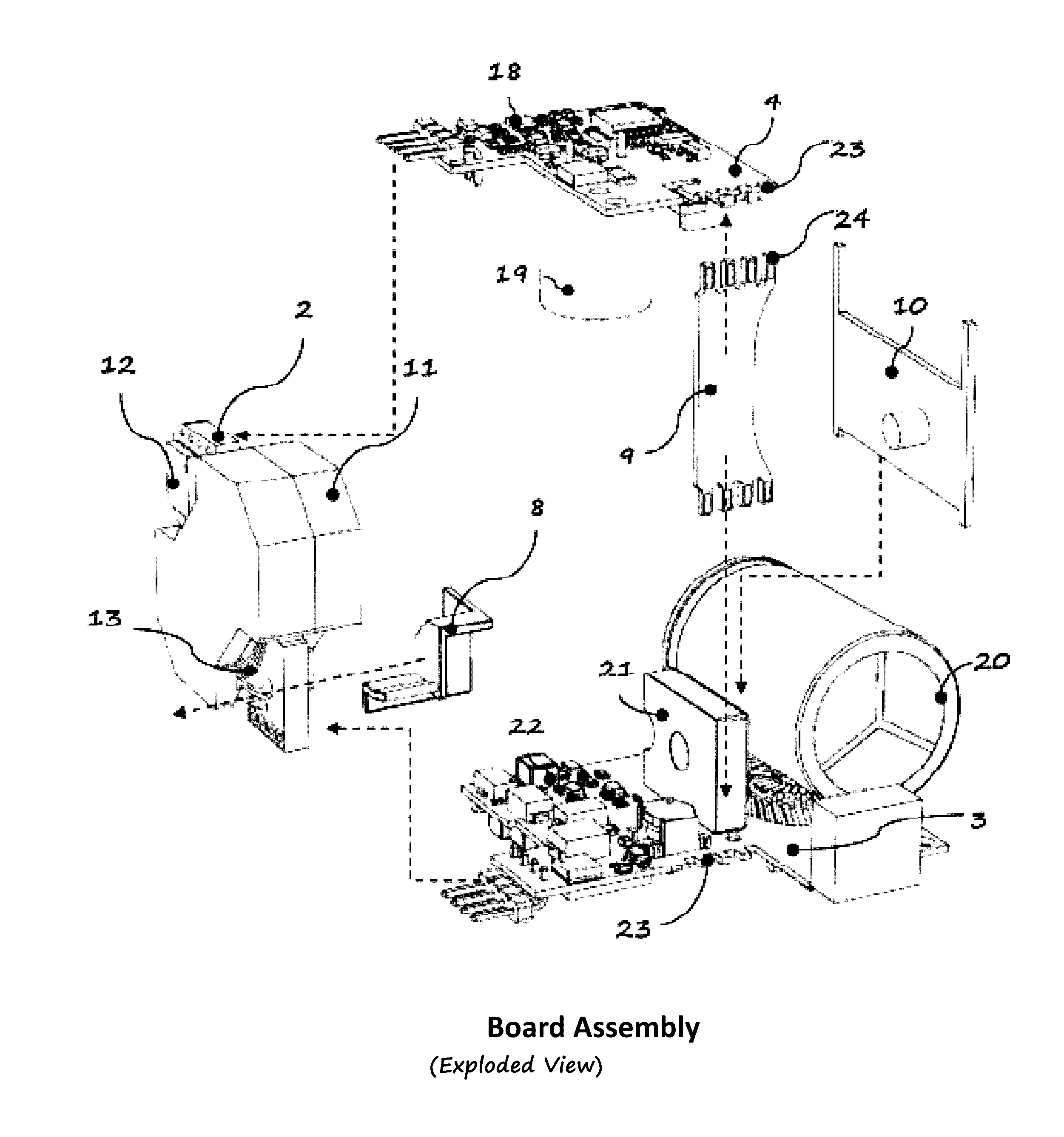
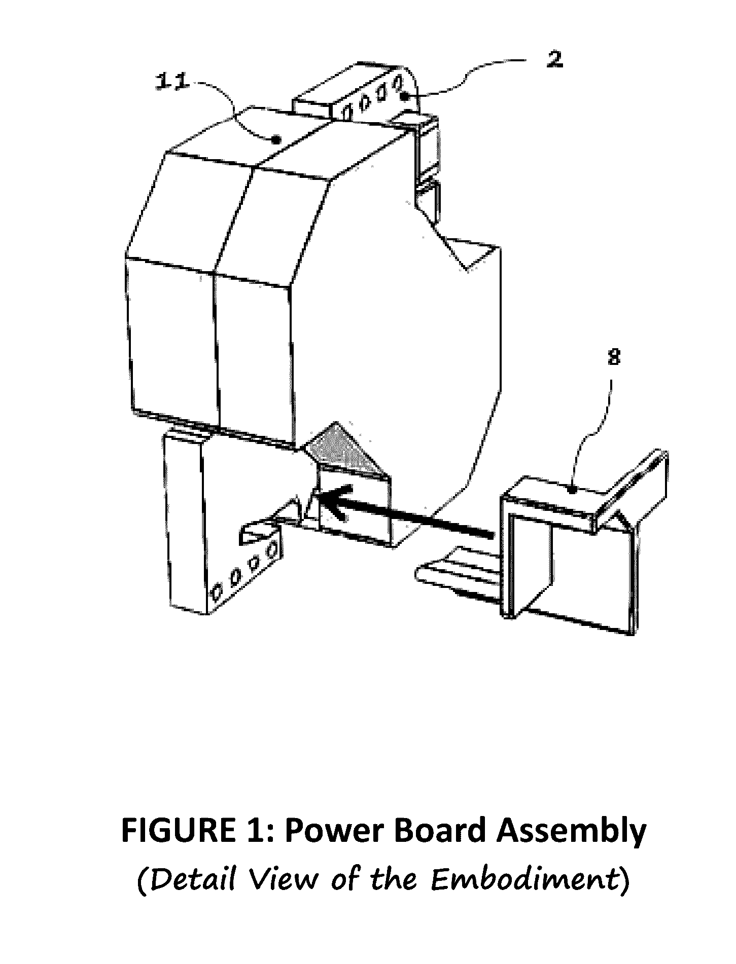
[0024]Presented in FIG. 1 is a typical arrangement of a power board assembly of the embodiment. In this figure, a typical power board (2) contains a transformer core (11) arranged in a board, which comprises of primary and secondary circuit. Moreover, the transformer can be set as part of either the primary or the secondary circuit. Such case, appropriate electrical isolation is vital between primary and secondary circuits, as well as the transformer core relative to each of the circuit and electrical components of each circuit. In this embodiment, the transformer core configured as part of the secondary circuit. The succeeding drawings will describe the importance of this particular arrangement of the transformer in relation to achieving the main goal of this invention.

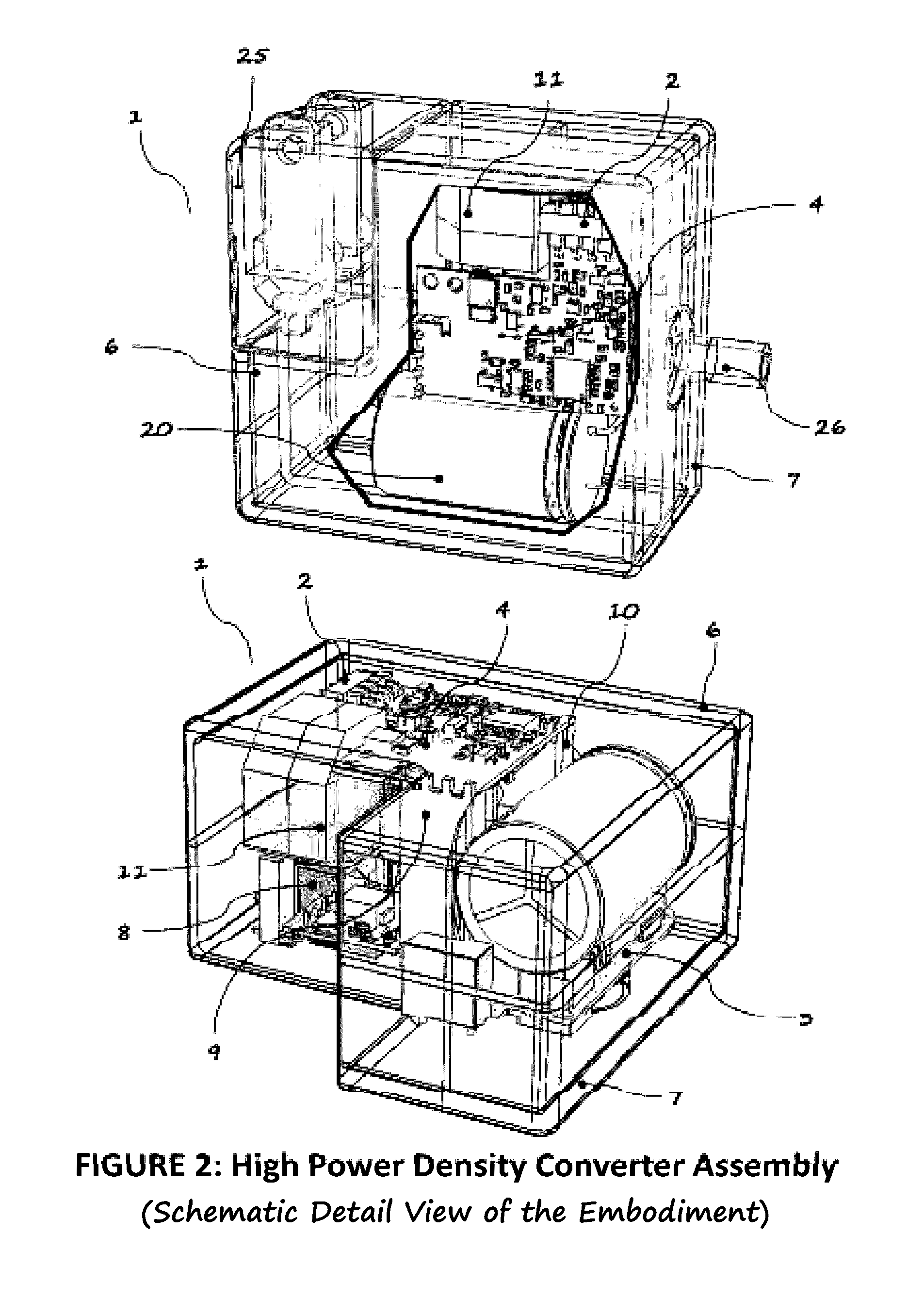
[0025]Presented in FIG. 2a, is the present invention showing the over-all physical profile of the embodiment of a high power density converter (1). It comprises of an AC plug (25) which is retractable and removable t...


PUM


Abstract

Meeting todays requirement in power supply technology demands significant technological advancement in optimizing circuit topology, components and materials, thermal and packaging designs. These requirements are being pushed mainly by continuously increasing power density and efficiency requirements. Ultimately, these trends will come to a point whereby limitations from the above mentioned technological advancements is dependent on one of the above, which is the packaging design. To realize this dependence, we need to look at the growing power systems for modern equipment out there. Let us enumerate some of the available AC adapters in terms of power densities of a 45 W adapter. Firstly, square type architecture introduced by Apple is about 7 W/in3, considering the packaging has a profile limitation whereby its AC plug is removable thus occupying relatively bigger chunk of the volume. The next one is by Asus of similar profile to Apple incorporating the AC Plug eliminating the socket assembly in the packaging; which packs about 9 W/in3. Lastly, the typical rectangular profile by Eos which is about 7 W/in3. As for this particular embodiment it is about 40% smaller in profile, in contrast to the 45 W Apple packaging, with increase power density of about 12 W/in3. Packaging design method plays a great role in achieving the above requirements for a very high density converters.

Description

RELATED APPLICATION / CLAIM OF PRIORITY[0001]This Application is related to and claims priority from U.S. provisional application Ser. No. 61 / 914,664, filed Dec. 11, 2013, which application is incorporated by reference herein.FIELD OF THE INVENTION[0002]The present invention relates generally to converters particularly the AC to DC power adapter. A converter having strategically improved packaging in heightening the power density by tackling the overall construction of the housing and reducing its size.BACKGROUND OF THE INVENTION[0003]With the advent technological advancement in portable computing and mobile devices, the trends in designing the above devices are leaning towards portability and miniaturization. In accordance to the above advancements, the converter particularly the AC to DC power adapter correspondingly driven to the same development as well as pushing the power density and efficiency to its limits.[0004]The present disclosure relates to converters and, particularly, A...

Claims


Application Information

Patent Timeline
Patent Type & Authority Applications(United States)
IPC IPC(8): H02M7/00H02M7/21H05K1/14H05K1/02H05K9/00H05K1/18
CPCH02M7/003H05K9/0071H05K1/181H05K1/14H05K2201/10015H02M7/21H05K2201/042H05K2201/062H05K2201/10166H05K1/0203H05K1/0256H05K3/366H05K2201/044H05K2201/047H05K2201/09063H05K2201/0999
Inventor JITARU, IONELPOYNTON, IANVELASCO, ENRIQUE
Owner ROMPOWER ENERGY SYST
Why Eureka
Try Eureka