Eureka AIR delivers breakthrough ideas for toughest innovation challenges, trusted by R&D personnel around the world.

Fan Blade Tip as a Cutting Tool

Active Publication Date: 2016-12-15
RAYTHEON TECH CORP
View PDF7 Cites 4 Cited by
  • Summary
  • Abstract
  • Description
  • Claims
  • Application Information

AI Technical Summary

Benefits of technology

The patent describes a method to reduce frictional heating between the airfows and the engine case in a gas turbine engine. The method involves providing oblique surfaces on the tips of the airfows, which are slanted away from the casing. This setup helps to decrease frictional heating and improve wear resistance.

Problems solved by technology

However, during operation, the erosion resistant coating may degrade or peel off the fan blade due to excessive blade tip heating when the blade tips rub against the abradable seal.
This has been determined to be caused by a combination of excessive heat generation by friction, the low thermal conductivity of the abradable material and high thermal conductivity of the blade material.

Method used


Image

  • Fan Blade Tip as a Cutting Tool
  • Fan Blade Tip as a Cutting Tool
  • Fan Blade Tip as a Cutting Tool

Examples


Embodiment Construction

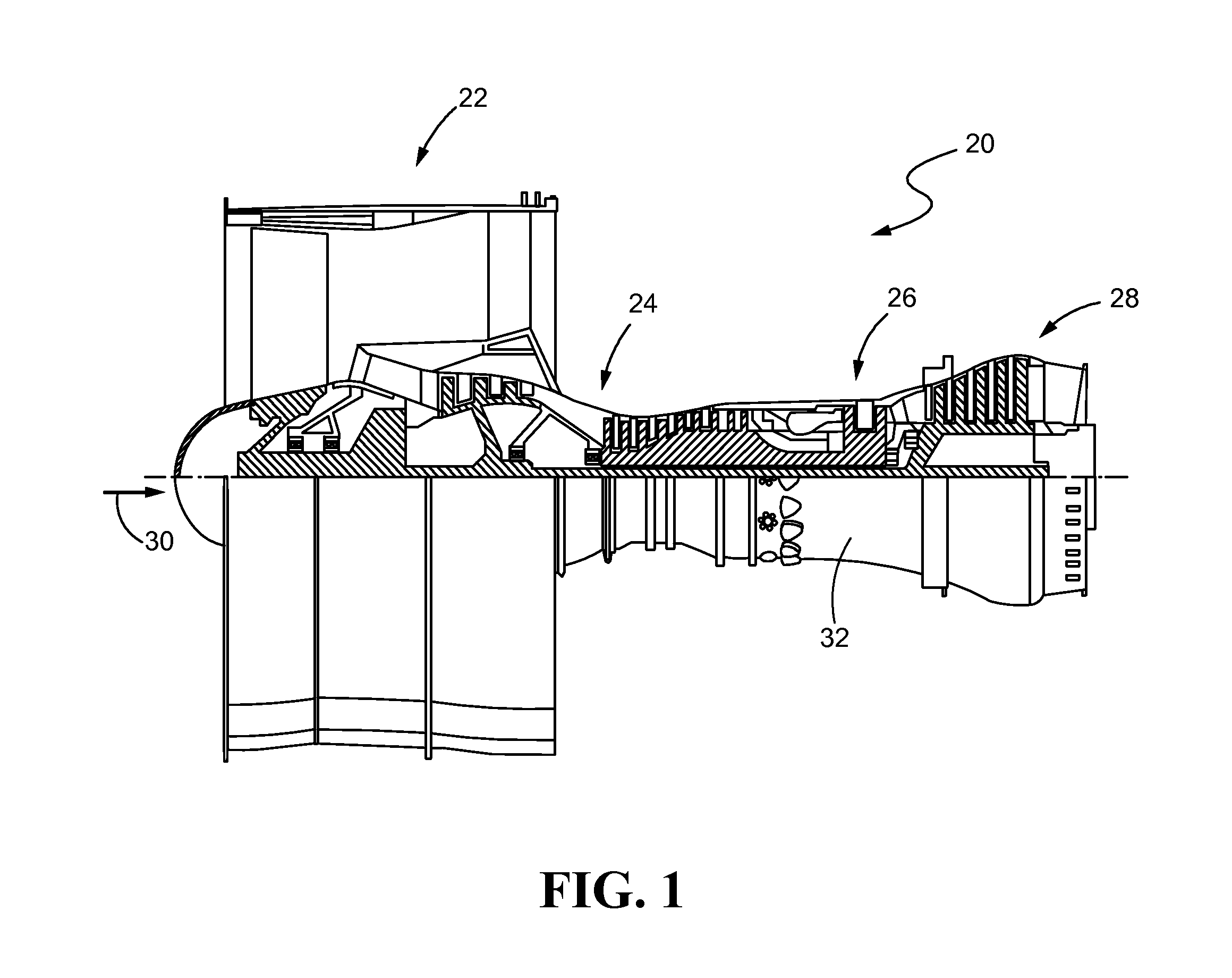
[0039]Referring now to the drawings, and with specific reference to FIG. 1, in accordance with the teachings of the disclosure, an exemplary gas turbine engine 20 is shown. The gas turbine engine 20 may generally comprise a fan section 22 which draws ambient air into the engine 20, a compressor section 24 where air is pressurized, a combustor 26 downstream of the compressor section which mixes and ignites the compressed air with fuel and thereby generates hot combustion gases, a turbine section 28 downstream of the combustor 26 for extracting power from the hot combustion gases, and an annular flow path 30 extending axially through each. A generally cylindrical engine casing 32 may circumscribe the fan section 22, compressor section 24, combustor section 26, and turbine section 28. Gas turbine engine 20 may be used on an aircraft for generating thrust or power, or in land-based operations for generating power as well.

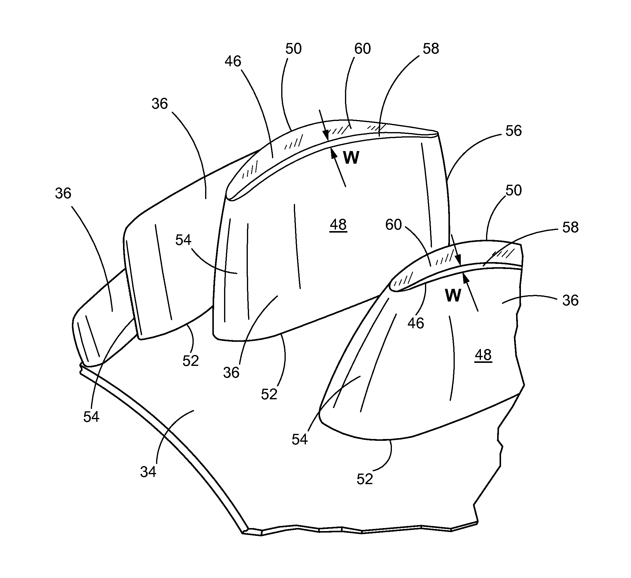
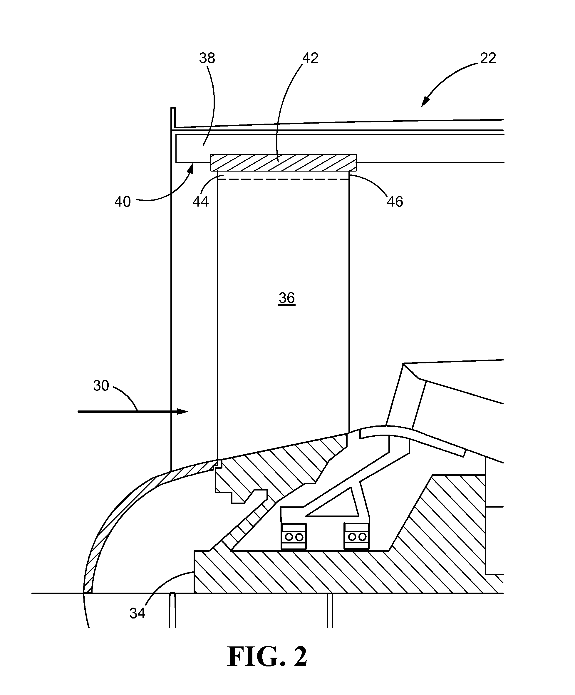
[0040]Turning now to FIGS. 2-4, with continued reference to FIG. 1...


PUM

PropertyMeasurementUnit
Angleaaaaaaaaaa
Angleaaaaaaaaaa
Widthaaaaaaaaaa

Abstract

An airfoil for a gas turbine engine is disclosed. The airfoil may include a first side, and a second side opposite the first side. The first side and the second side may extend axially from a leading edge to a trailing edge and radially from a base to a tip. The tip may include an oblique surface between the first side and the second side.

Description

FIELD OF THE DISCLOSURE[0001]This Application is a non-provisional patent application claiming priority under 35 USC §119(e) to U.S. Provisional Patent Application Ser. No. 62 / 007,567 filed on Jun. 4, 2014.FIELD OF THE DISCLOSURE[0002]The present disclosure relates generally to gas turbine engines and, more particularly, to airfoils in a gas turbine engine.BACKGROUND OF THE DISCLOSURE[0003]Gas turbine engines may typically include a fan, a compressor, a combustor, and a turbine, with an annular flow path extending axially through each. Initially, the fan, which is powered by the turbine, draws ambient air into the engine. Part of the air flows through the compressor where it is compressed or pressurized. The combustor then mixes and ignites the compressed air with fuel, generating hot combustion gases. These hot combustion gases are then directed from the combustor to the turbine where power is extracted from the hot gases by causing blades of the turbine to rotate. The other part o...

Claims


Application Information

Patent Timeline
IPC IPC(8): F01D5/20F01D5/28F04D29/32F02C7/28F04D29/52F04D29/16F02C3/04F01D11/12F04D29/38
CPCF01D5/20F01D11/122F01D5/288F04D29/324F04D29/325F04D29/384F05D2240/55F04D29/164F02C3/04F02C7/28F05D2220/32F05D2300/611F04D29/526F05D2250/192Y02T50/60
Inventor HANSEN, JAMES O.GUO, CHANGSHENG
Owner RAYTHEON TECH CORP
Why Eureka
Eureka Blog
Learn More