
Method and apparatus for controlling an HVAC system

a technology for heating ventilation and air conditioning, applied in lighting and heating apparatus, heating types, instruments, etc., can solve the problems of cumbersome updating, wasting energy, and imposing higher costs on their owners, and achieves convenient and efficient behavior, without making annoying sounds.

Active Publication Date: 2016-12-15
SENSIBO
View PDF7 Cites 46 Cited by
  • Summary
  • Abstract
  • Description
  • Claims
  • Application Information

AI Technical Summary

Benefits of technology

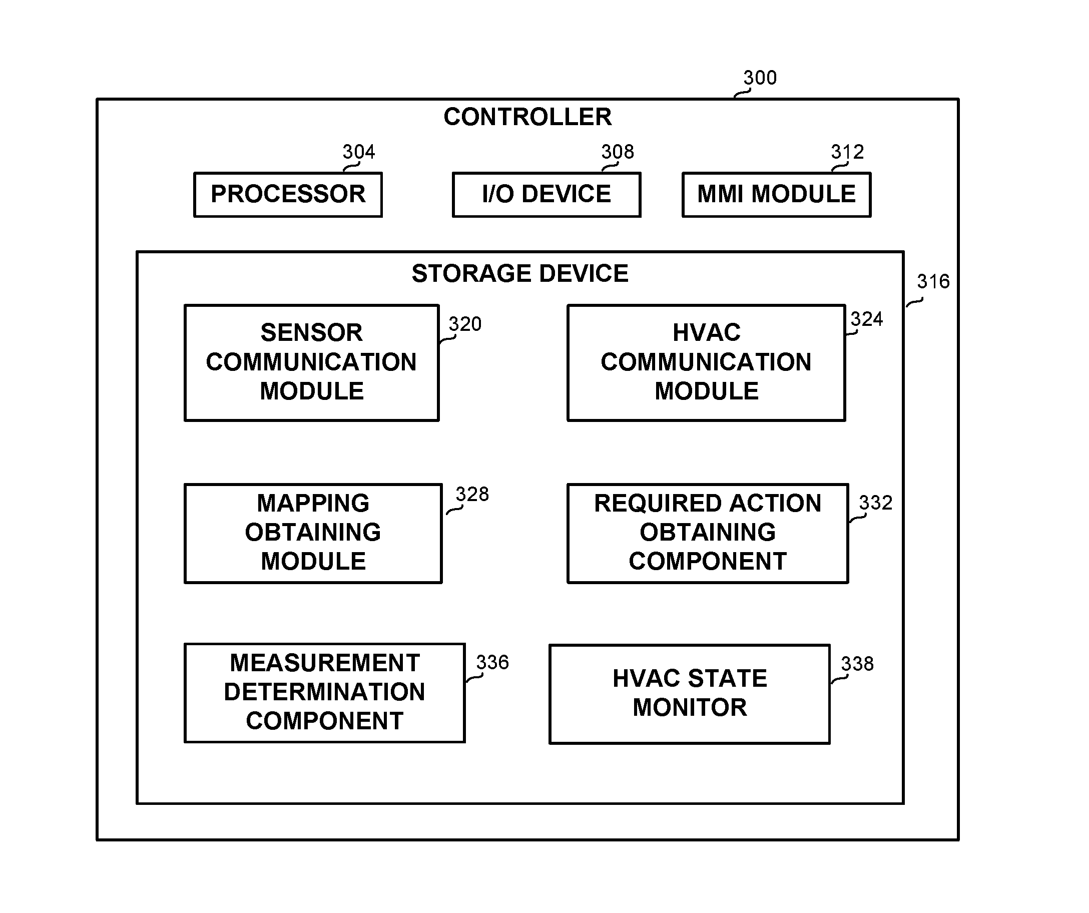
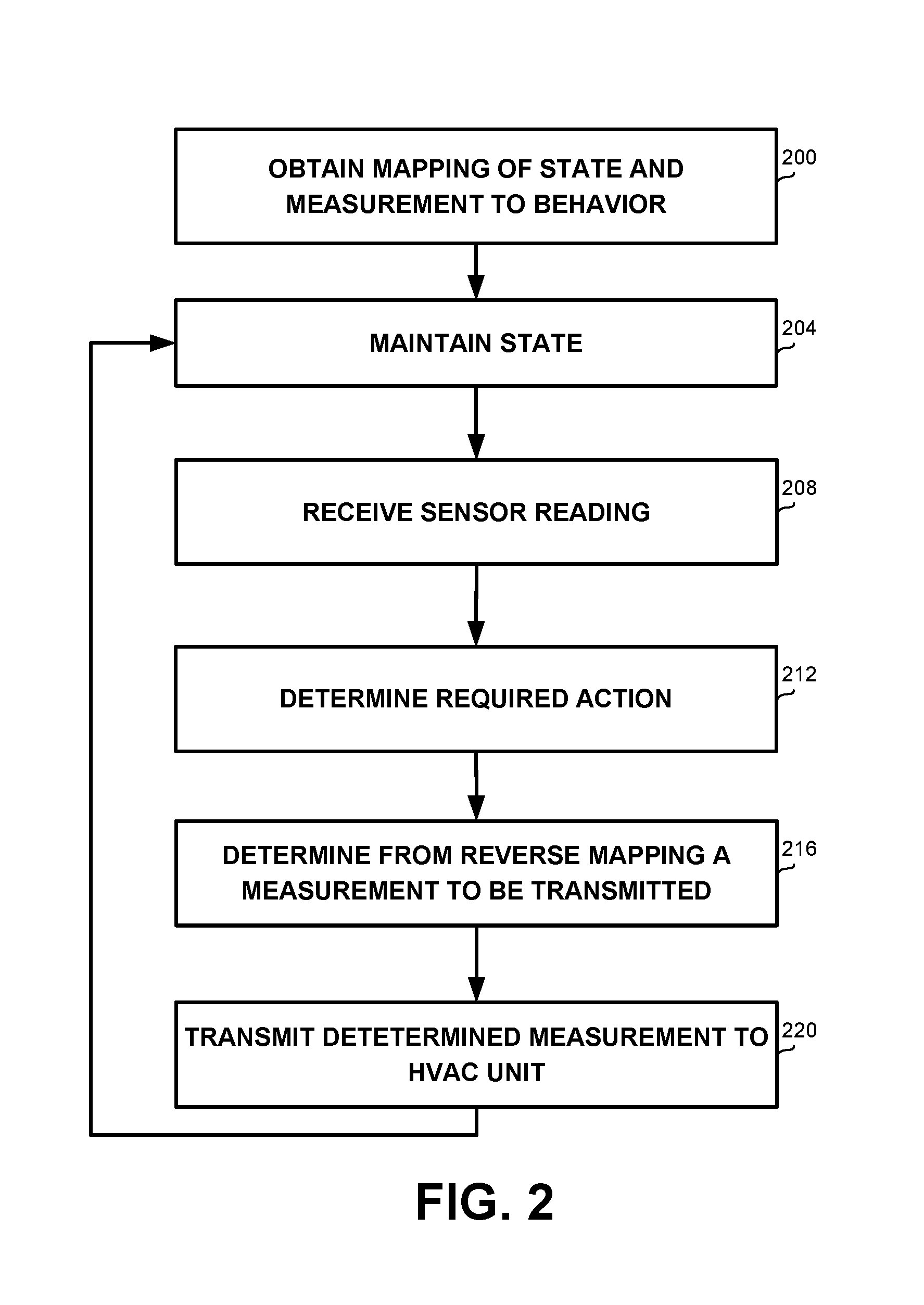
This patent describes a controller and computerized device that can communicate with a heating, ventilation, or air-conditioning (HVAC) unit to control its operation. The controller or computerized device obtains a mapping between the HVAC unit's states and its corresponding actions, and based on this mapping, determines the action to be taken by the HVAC unit. This mapping can be based on readings from sensors or on the current state of the HVAC unit. The controller or computerized device can also transmit the determined action to the HVAC unit using different types of messages. The technical effect of this patent is to provide a more efficient and effective way to control the operation of HVAC units by automating the process of mapping and determining appropriate actions based on sensor readings.

Problems solved by technology

Thus, although technology advances and better, more economic and more efficient HVAC systems become available, many older units are still being used, working in suboptimal manner, thus wasting energy and exerting higher cost on their owners.
Some units may be provided with a way to update their control algorithm, but such units are rare, and updating is cumbersome.
However, it is difficult to replace the control algorithm without having direct access to the unit's control parameters such as compressor on / off, fan speed, or the like, or to measurements sensed by the unit, such as temperature.
Thus, when cooling, one could set the HVAC target temperature, for example, to 30° C. for stopping the compressor, and to 16° C. for starting it (and vice versa when heating), but this will generally not provide optimal results.
Thus, using the remote control commands to replace the control algorithm of the HVAC will cause the generation of such sound for each command, which may annoy the user, particularly when the user is asleep.

Method used


Image

  • Method and apparatus for controlling an HVAC system
  • Method and apparatus for controlling an HVAC system
  • Method and apparatus for controlling an HVAC system

Examples


Embodiment Construction

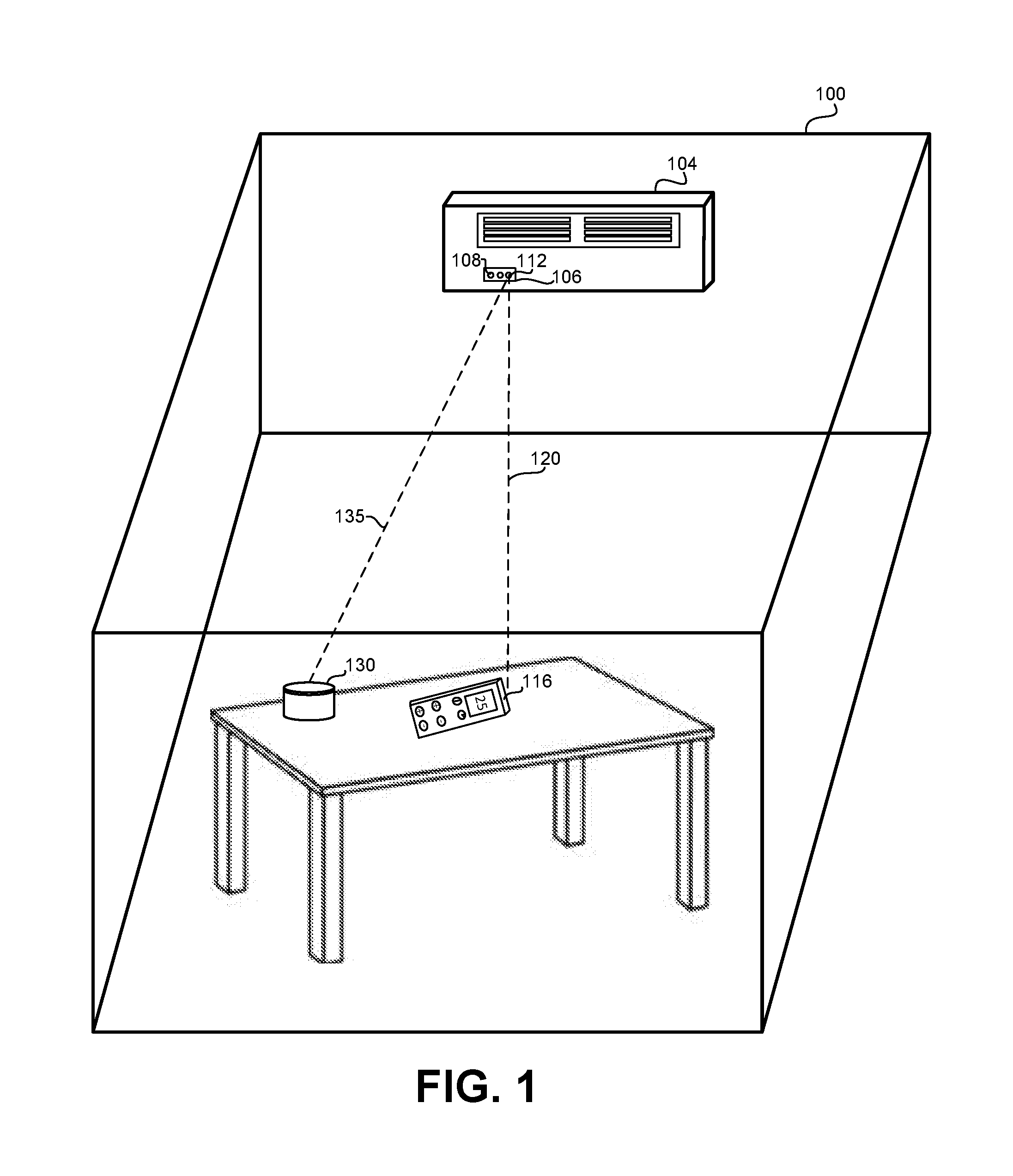
[0014]One technical problem dealt with by the disclosed subject matter is the need to replace the control algorithm and mechanism of HVAC units. In some cases, replacing the control algorithm and mechanism of the HVAC units may enable more energy-efficient control without replacing the whole unit. In some cases, the new control algorithm and mechanism may be configured to control the HVAC unit without causing the HVAC to make audible sounds or other sensory cues that may disturb a person staying in the vicinity of the HVAC unit. In some cases, a smart grid system may decide to change the control of an HVAC unit. Additionally or alternatively, the control algorithm could be personalized to the person currently using the HVAC unit.

[0015]Some HVAC units are configured to emit an audible sound (e.g., “beep”), in response to receiving a command, such as via an Infra Red (IR) signal emitted by a remote control. The audible sound may indicate to a user that the command was received and is ...


PUM


Abstract

A method and controller for Heating Ventilation or Air-Conditioning (HVAC), the controller having a processing unit and a storage device, the controller comprising: a mapping obtaining module for obtaining a mapping between a pair of a state of an HVAC unit and an action of the HVAC unit and between a measurement; an action determination component for determining an action to be taken by the HVAC unit in accordance with a current state of the HVAC unit; a measurement determination component for obtaining from the mapping a synthesized measurement that when transmitted to the HVAC unit is adapted to cause the HVAC unit to perform the action; and an HVAC communication module for transmitting the synthesized measurement to the HVAC unit.

Description

CROSS-REFERENCE TO RELATED APPLICATION[0001]This application claims the benefit of U.S. Provisional Application No. 61 / 867,073 filed Aug. 18, 2013, entitled “A method for seamlessly replacing a control algorithm of an HVAC system using only IR commands”, and of U.S. Provisional Application No. 61 / 992,993 filed May 14, 2014, entitled “A completely external and cable free device and system that connects air conditioners to the internet and uses sensory data to provide superior comfort and energy savings”, both of which are hereby incorporated by reference in their entirety.TECHNICAL FIELD[0002]The present disclosure relates to controlling a Heating, Ventilation, or Air Conditioning (HVAC) system in general, and for replacing a control system of an existing HVAC system, in particular.BACKGROUND[0003]Heating, Ventilation, or Air Conditioning (HVAC) systems are usually purchased and installed, and then used for many years. Thus, although technology advances and better, more economic and ...

Claims


Application Information

Patent Timeline
Patent Type & Authority Applications(United States)
IPC IPC(8): F24F11/00G05B15/02
CPCF24F11/006F24F11/0012F24F2011/0068G05B15/02F24F2011/0061F24F11/0015F24F11/30F24F2110/10F24F2110/20F24F11/62F24F11/63F24F11/56F24F11/64F24F11/523
Inventor ROTH, RANENBAR, OMER
Owner SENSIBO
Learn More