High-precision time of flight measurement systems

a measurement system and high-precision technology, applied in the field of distance measurements, can solve the problems of difficult to perceive the orientation of objects, visual or imaging systems only slightly better, etc., and achieve the effect of increasing the sensitivity and the range of the receiver

Active Publication Date: 2016-12-15
HUMATICS CORP
View PDF7 Cites 105 Cited by
  • Summary
  • Abstract
  • Description
  • Claims
  • Application Information

AI Technical Summary

Benefits of technology

[0013]In some embodiments the receiver includes at least one antenna configured to receive the electromagnetic signal at a first frequency, and a multiplier coupled to the at least one antenna to receive the electromagnetic signal at the first frequency and that provides a multiplied signal having a harmonic component at a second frequency that is a harmonic multiple of the first frequency. In some embodiments the receiver includes a power source that is configured to normally bias the multiplier to a biased off state and that is configured to bias on the multiplier to an on state in response to receipt of the auxiliary wireless signal configured with the unique code to target the receiver. In some embodiments the power source is further configured to forward bias the multiplier to increase a sensitivity and range of the receiver. In some embodiments the receiver has no active components other than the multiplier, which is configured to normally be off so as to require substantially no power. In some embodiments the power source is one of a low power battery source or power is derived by one or more energy harvesting techniques. In some embodiments the antenna comprises a single antenna for both receiving the electromagnetic signal at the first frequency and transmitting the multiplied signal at the second frequency. In some embodiments the receiver includes the multiplier integrated with the antenna element.

Problems solved by technology

Orientation of the object is difficult to perceive with such systems, and visual or imaging systems yield only slightly better results because they tend to be limited to two dimensional images of the object which may mislead a system or observer as to the actual orientation of the object.

Method used


Image

  • High-precision time of flight measurement systems
  • High-precision time of flight measurement systems
  • High-precision time of flight measurement systems

Examples


example purposes

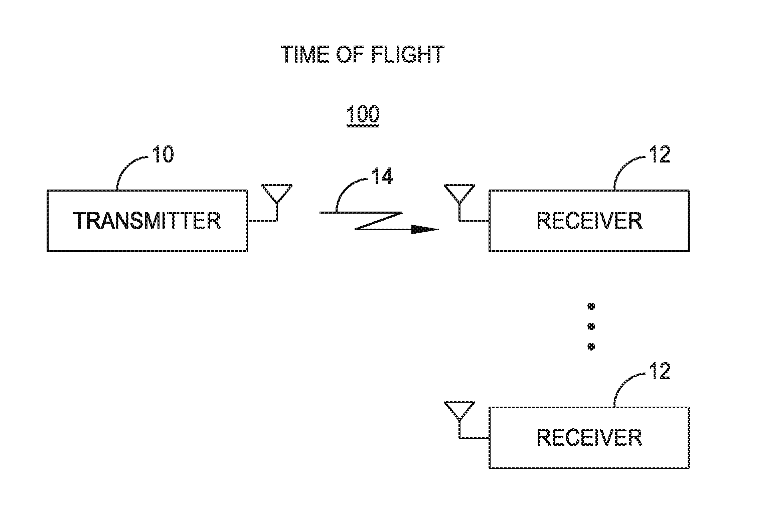
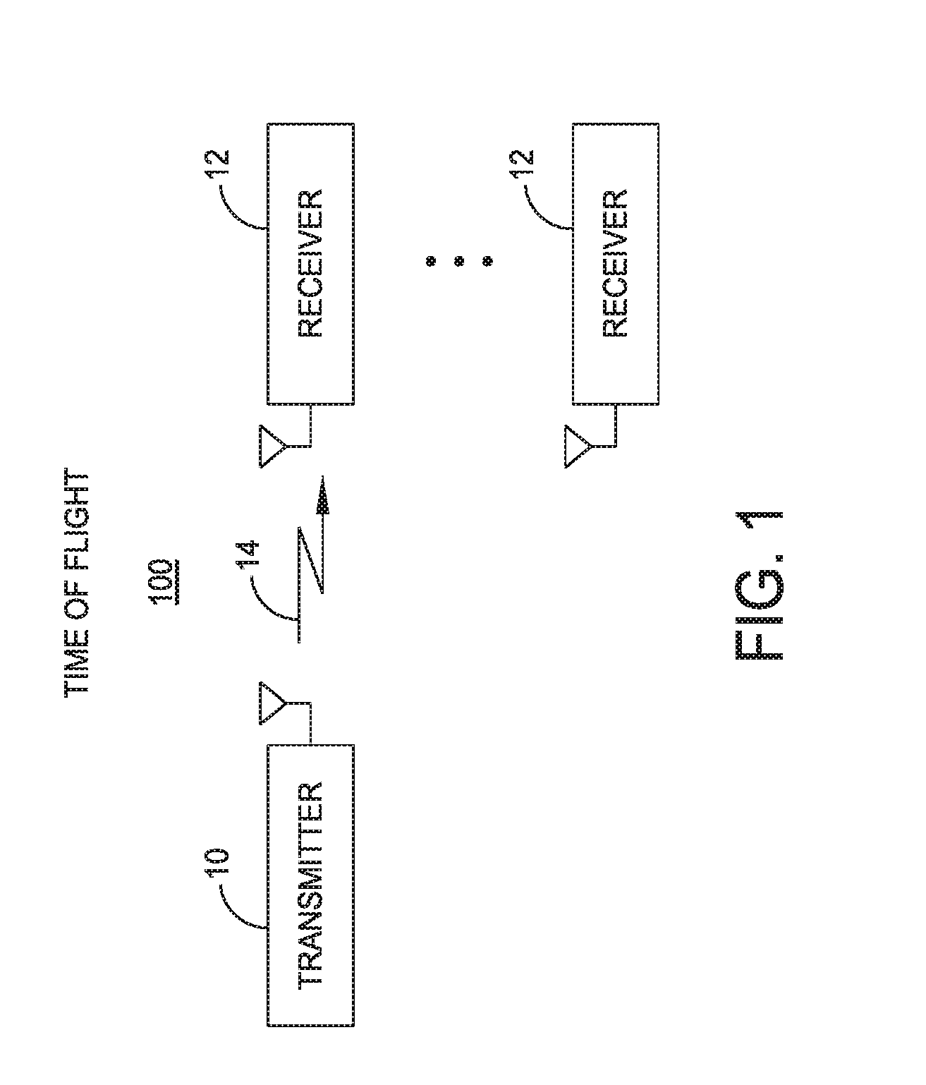
[0175]According to aspects and embodiments of any of the TOF ranging systems disclosed herein, the system can be used for measuring precise travel times between two points so as to measure changes in propagation characteristics of the medium.

[0176]According to aspects and embodiments of any of the TOF ranging systems disclosed herein, the system can be used as a synthetic aperture for providing position information of any measured quantity in a two or three dimensional space. For example, light intensity in a room may be measured at various positions, for instance by moving around a light sensor equipped with a TOF ranging device, and the system may record the light intensity at the precise TOF locations to enable a two or three dimensional model or image to be re-created. The light intensity information could include multiple channels, such as for red, green, and blue color information. Any measurable quantity of interest may be 2-D or 3-D mapped. Other measured quantities might in...


PUM


Abstract

A system and method is disclosed for measuring time of flight to an object. A transmitter transmits an electromagnetic signal and provides a reference signal corresponding to the electromagnetic signal. A receiver receives the electromagnetic signal and provides a response signal corresponding to the received electromagnetic signal. A detection circuit is configured to determine a time of flight between the transmitter and the receiver based upon the reference signal and the response signal.

Description

CROSS-REFERENCE TO RELATED APPLICATIONS[0001]This application claims the benefit of co-pending U.S. provisional application Ser. No. 62 / 175,819 filed Jun. 15, 2015; 62 / 198,633 filed Jul. 29, 2015; 62 / 243,264 filed Oct. 19, 2015; 62 / 253,983 filed Nov. 11, 2015; 62 / 268,727, 62 / 268,734, 62 / 268,736, 62 / 268,741, and 62 / 268,745, each filed Dec. 17, 2015; 62 / 271,136 filed Dec. 22, 2015; 62 / 275,400 filed Jan. 6, 2016; and 62 / 306,469, 62 / 306,478, and 62 / 306,483, each filed Mar. 10, 2016, each of which is herein incorporated by reference in its entirety for all purposes.BACKGROUND[0002]1. Field of the Disclosure[0003]The present disclosure generally relates to distance measurements, and more particularly to measuring distances using electromagnetic signals.[0004]2. Discussion of Related Art[0005]Tracking and ranging of an object typically relies on reflected signals from the object, as in radar tracking and ranging, and yields only bulk information about the relative position and movements of...

Claims


Application Information

Patent Timeline
Patent Type & Authority Applications(United States)
IPC IPC(8): G01S13/34G01S7/35
CPCG01S13/34G01S2007/356G01S2007/358G01S7/352G01S13/878G01S13/42G01S13/76G01S5/10H04W4/029G01S5/14G01S13/74G01S13/82G01S2205/01G01S7/356G01S7/358G01S5/021G01S5/0247G01S5/0294G01S7/003G01S13/66G01S13/885
Inventor MINDELL, DAVID A.CHARVAT, GREGORY L.COHEN, GARY A.YOERGER, DANA R.
Owner HUMATICS CORP
Why Eureka
Try Eureka