
Catalytic reforming processes

a technology of catalytic reforming and process, applied in the field of aromatic compound production, can solve the problems of significant cost increase, process operation at a lower temperature, and limit the methods and catalysts, so as to reduce the amount of thermal cracking and minimize the effect of yield loss

Active Publication Date: 2016-12-22
UOP LLC
View PDF1 Cites 3 Cited by
  • Summary
  • Abstract
  • Description
  • Claims
  • Application Information

AI Technical Summary

Benefits of technology

This patent describes a process for reducing thermal cracking in a catalytic reformer unit, which can minimize yield loss and increase efficiency. The process involves mixing a thermal cracking inhibitor, such as an olefin stream, with the feed stream, the heated feed stream, or the reformate effluent stream to reduce thermal cracking and increase the yield of valuable products. Additionally, a second reforming zone with catalyst can be used to further reduce thermal cracking.

Problems solved by technology

However, there are limits to the methods and catalysts presented in these patents, and which can entail significant increases in costs.
However, the reforming process is operated at a lower temperature due to the thermal cracking and the metal catalyzed coking that occurs as the temperature is increased.
However, increasing the temperatures increases the formation of coke on the catalyst, and more rapidly deactivates the catalyst.
Increasing temperatures also increases thermal cracking for the heavier hydrocarbons, and can start or increase metal catalyzed coking on the surfaces of the reactor vessel or piping used to transport the hydrocarbons to the reformer.
The thermal cracking of naphtha feed and intra-reactor reformed product streams lead directly to yield loss through the production of light (one to four carbon) hydrocarbons.
While catalytically beneficial this design also requires increased temperatures in heaters and transfer lines to the terminal reactors giving corresponding increases in thermal cracking yield losses.
Although thermal cracking exists in all reforming units the potential for yield loss is potentially higher in such designs due to the elevated temperatures intrinsically required by the process.

Method used


Image

  • Catalytic reforming processes
  • Catalytic reforming processes

Examples


Embodiment Construction

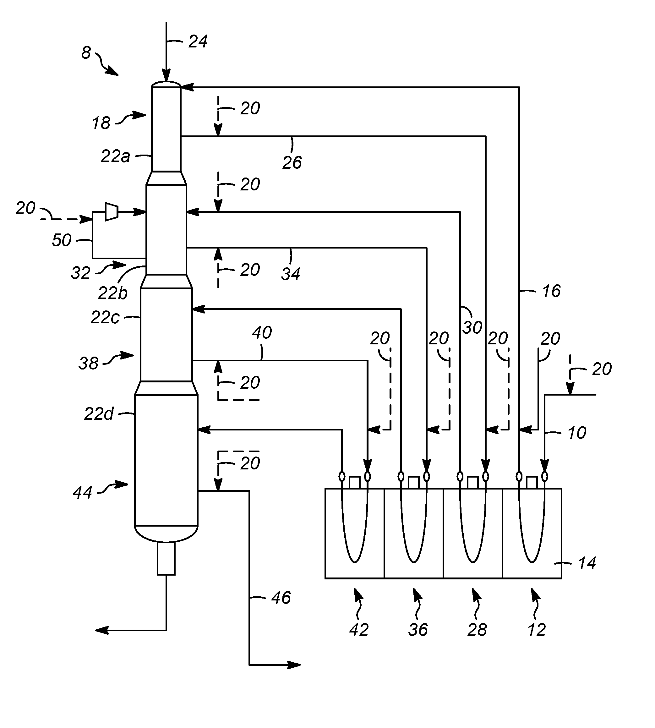
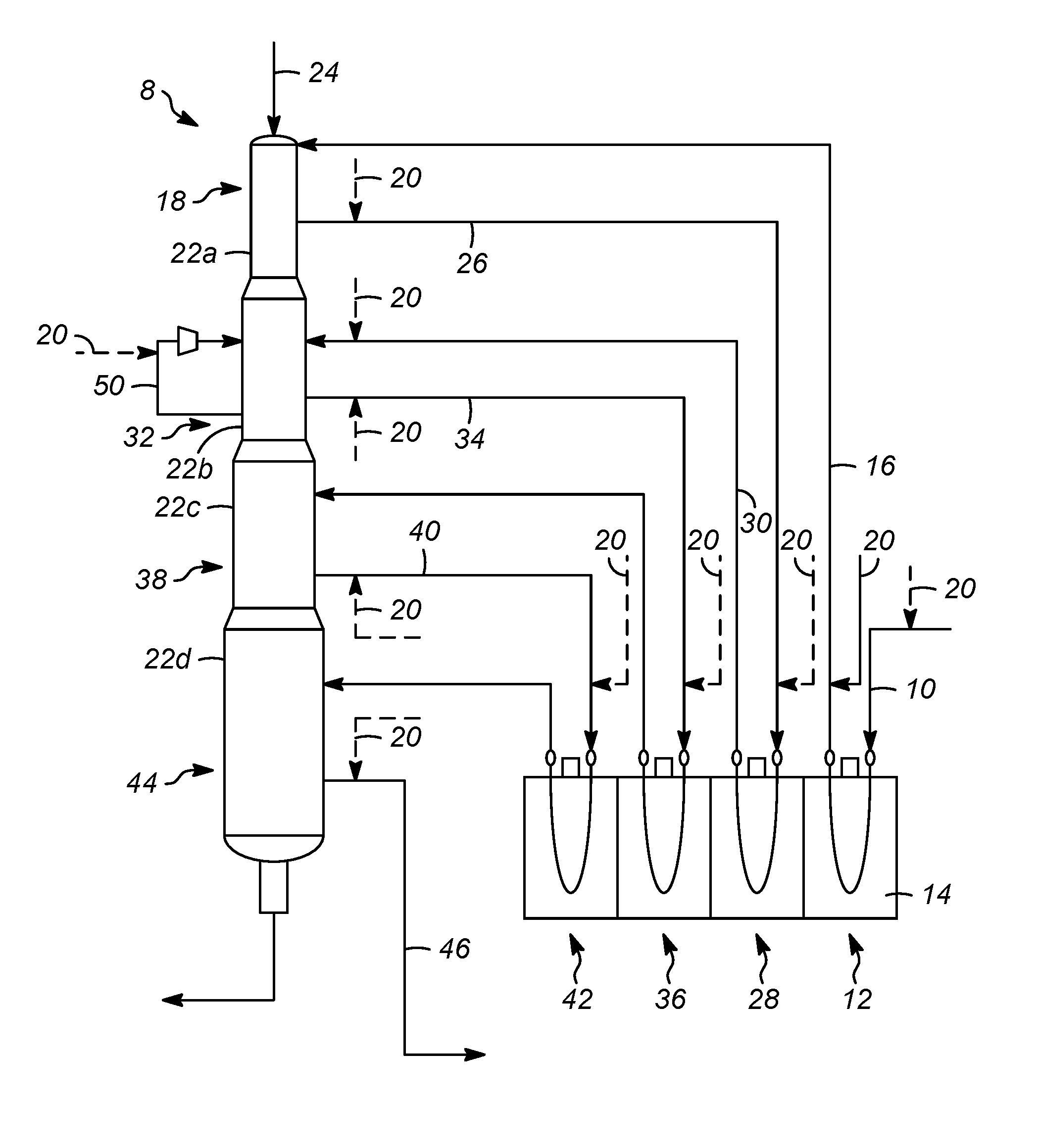
[0026]As mentioned above, one or more processes have been invented to reduce the amount of thermal cracking associated with a catalytic reformer unit. Thermal cracking of hydrocarbons proceeds through a unimolecular reaction in which a hydrogen is abstracted from the hydrocarbon to produce a radical species, followed by carbon-carbon bond breaking in the position beta to the formed radical. The primary factors influencing the thermal cracking rate, and thus yield loss, are temperature and residence time at elevated temperatures. The cracking rate is also a function of the molecule's carbon number, as well as attached functional groups such branches, double bonds, and phenyl groups. It is believed that olefins, preferably light olefins may be used as a thermal cracking inhibitor in the catalytic reformer unit.

[0027]This inhibition of thermal cracking is due to the ability of, for example, propylene to form a stable radical species. The formed allylic radical is stabilized by the pres...


PUM


Abstract

Processes for catalytic reforming in which a cracking inhibitor, such as an olefin, or a light olefin, is used to inhibit thermal cracking of larger hydrocarbons in non-reactive zones. The cracking inhibitor may be added at various positions through the processes, such as in the recycle gas stream, before a heater, before a stream is passed into a reforming zone, after an effluent stream is recovered from a reforming zone. A molar ratio of cracking inhibitor to hydrocarbons in stream may be between 0.01 and 0.2.

Description

CROSS-REFERENCE TO RELATED APPLICATION[0001]This application claims priority from Provisional Application No. 62 / 180,335 filed Jun. 16, 2015, the contents of which are hereby incorporated by reference.FIELD OF THE INVENTION[0002]This invention relates generally to processes for the production of aromatic compounds, and in particular processes in which include a catalyst for reforming hydrocarbons to form aromatic compounds such as benzene, toluene and xylenes from a naphtha feedstream through changing process conditions.BACKGROUND OF THE INVENTION[0003]The reforming of petroleum raw materials is an important process for producing useful products. One important process is the separation and upgrading of hydrocarbons for a motor fuel, such as producing a naphtha feedstream and upgrading the octane value of the naphtha in the production of gasoline. However, hydrocarbon feedstreams from a raw petroleum source include the production of useful chemical precursors for use in the productio...

Claims


Application Information

Patent Timeline
IPC IPC(8): C10G35/04C10G59/02
CPCC10G35/04C10G2300/80C10G2400/30C10G59/02
Inventor HOLMGREEN, ERIKJIN, LINLAPINSKI, MARK P.DEVEREUX, BRIAN M.
Owner UOP LLC
Learn More