Luminaire, modular surface covering arrangement and luminaire kit

Active Publication Date: 2016-12-22
SIGNIFY HLDG BV
View PDF2 Cites 2 Cited by
  • Summary
  • Abstract
  • Description
  • Claims
  • Application Information

AI Technical Summary

Benefits of technology

[0018]According to another aspect, there is provided a modular surface covering arrangement such as a modular ceiling arrangement, comprising a plurality of covering tiles supported by a support grid and at least one such a troffer. Such a modular surface covering arrangement may exhibit high uniformity due to the excellent flatness and side wall linearity of the luminaire, and moreover may be provided at lower cost than existing modular surface covering arrangements.
[0019]According to yet another aspect, there is provided a luminaire kit for assembling the luminaire of any of the above embodiments, the kit comprising a cover plate including an light exit window and a region surrounding the light exit window, at least a part of said region comprising a plurality of first fixing members selected from one of a plurality of holes and a plurality of protrusions; a reflector delimiting an inner volume and comprising at least one edge comprising a plurality of second fixing members, which are a plurality of holes in case the first fixing members are a plurality of protrusions and which are a plurality of protrusions in case the first fixing members are a plurality of holes, said protrusions dimensioned to extend through said holes, wherein the first fixing members and second fixing members are positioned for mating with each other; and a plurality of solid state elements within the inner volume. Such a luminaire kit facilitates the assembly of the luminaire of at least some of the embodiments of the present invention in a s

Problems solved by technology

It is not straightforward to provide a luminaire having the desired flatness and side wall linearity in a cost-effective manner.
The manufacturing of such luminaires is typically quite c

Method used


Image

  • Luminaire, modular surface covering arrangement and luminaire kit
  • Luminaire, modular surface covering arrangement and luminaire kit
  • Luminaire, modular surface covering arrangement and luminaire kit

Examples


Embodiment Construction

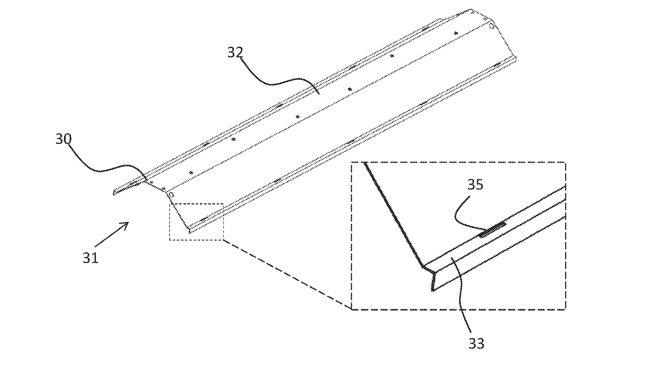
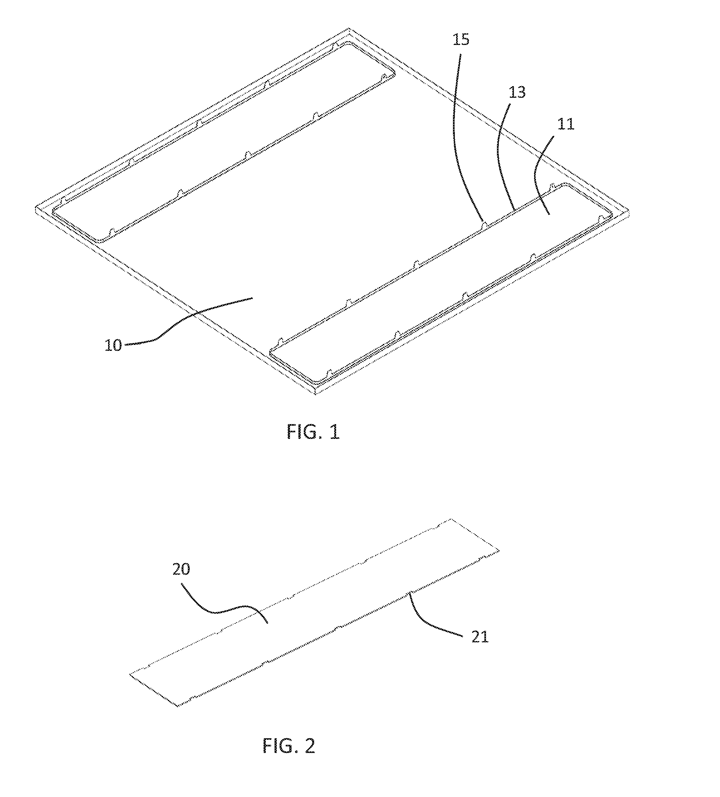
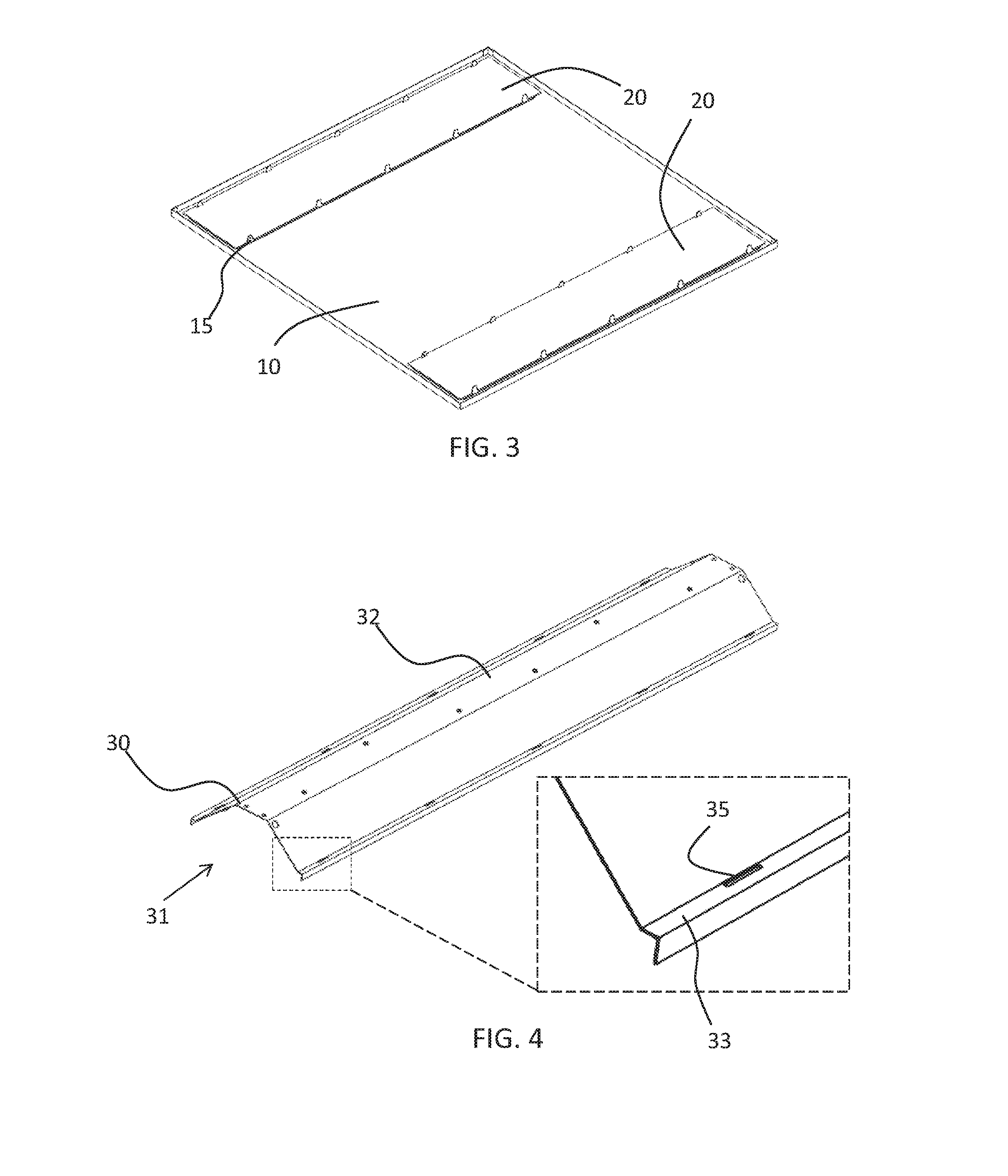
[0031]It should be understood that the Figures are merely schematic and are not drawn to scale. It should also be understood that the same reference numerals are used throughout the Figures to indicate the same or similar parts.

[0032]In the following, an example embodiment of the present invention will be described in terms of various components of a luminaire that are assembled in order to provide a luminaire according to the example embodiment. In some embodiments, the luminaire may form a troffer for a modular surface covering arrangement, e.g. a modular floor including the troffer or a modular ceiling arrangement, e.g. a PC or CP ceiling, including the troffer. Where the luminaire is implemented as such a troffer, it should be understood that the troffer may have any suitable dimension, e.g. a square outline of for instance 600×600 mm, an oblong outline such as for instance 300×1200 mm, or, when designed as a surface mounted luminaire, an outline of 200×1200 mm or any other suit...


PUM

PropertyMeasurementUnit
Volumeaaaaaaaaaa
Shapeaaaaaaaaaa
Surfaceaaaaaaaaaa

Abstract

A luminaire is disclosed comprising a cover plate including an light exit window and a region surrounding the light exit window, at least a part of said region comprising a plurality of first fixing members selected from one of a plurality of holes and a plurality of protrusions dimensioned to extend through said holes; a reflector having an inner volume and comprising at least one edge comprising a plurality of second fixing members, selected from the other of the plurality of holes and the plurality of protrusions dimensioned to extend through said openings; and a plurality of solid state elements within the inner volume, wherein the protrusions extend through the holes, each protrusion having a portion extending beyond the opening through which the protrusion extends, said portion being bent over an edge of the opening to secure the reflector on the cover plate, wherein the inner volume is delimited by the reflector and the cover plate and the solid state lighting elements are arranged to direct their luminous output towards the light exit window. A modular surface covering arrangement including such a luminaire and a kit for assembling such a luminaire are also disclosed.

Description

FIELD OF THE INVENTION[0001]The present invention relates to a luminaire such as a troffer for a modular surface covering arrangement.[0002]The present invention further relates to a modular surface covering arrangement including such a luminaire. The present invention yet further relates to a luminaire kit for assembling such a luminaire.BACKGROUND OF THE INVENTION[0003]In the illumination of work environments, e.g. office lighting, the visual quality of the lighting installation is an important factor in the perception of the lighting. This applies to both recessed and surface mounted lighting installations. The shape of the luminaires in such installations is an important design parameter to achieve the desired appearance of the lighting installation. A luminaire having a high degree of flatness and side wall linearity for instance facilitates the avoidance of unnecessary gaps between luminaires and other elements of the lighting installation, e.g. floor or ceiling tiles of for i...

Claims


Application Information

Patent Timeline
IPC IPC(8): F21K99/00F21V29/10F21V7/22F21S8/02F21V3/02
CPCF21K9/175F21S8/026F21Y2101/02F21V7/22F21V29/10F21V3/02F21S2/00F21V5/00F21V7/005F21V7/24F21V7/28F21V17/16F21Y2103/10F21Y2115/10F21K9/27F21Y2101/00
Inventor LIU, ALEX FENGADEMA, RIEMERJANKOW, MARIUSZZACH, ALEKSANDER
Owner SIGNIFY HLDG BV
Why Eureka
Try Eureka