Method and apparatus for coordinating solar lighting with grid powered lightin

Inactive Publication Date: 2016-12-22
ELLIS JEREMY
View PDF2 Cites 2 Cited by
  • Summary
  • Abstract
  • Description
  • Claims
  • Application Information

AI Technical Summary

Benefits of technology

The patent describes a device that attaches a solar light to a grid-powered light pole, allowing the solar light to be aligned with the grid-powered light pole. This device includes a reflector that directs the sunlight onto a triggering photocell, ensuring that the solar light operates in an orderly manner and reducing the need for battery power. The device is easy to install and can be produced in a cost-effective manner.

Problems solved by technology

In our current environment the use of solar lights is virtually universal, with little attention paid, however, to the over-all energy efficiencies that these very simple and trouble-free devices can provide.
Even in these peripheral locations, however, each such device is exposed to varying levels of sunlight exacerbated by varying levels of dust collection as well as varying intensities of reflected light and shading, resulting highly varied switching schedules as darkness begins to set in.

Method used


Image

  • Method and apparatus for coordinating solar lighting with grid powered lightin
  • Method and apparatus for coordinating solar lighting with grid powered lightin
  • Method and apparatus for coordinating solar lighting with grid powered lightin

Examples


first embodiment

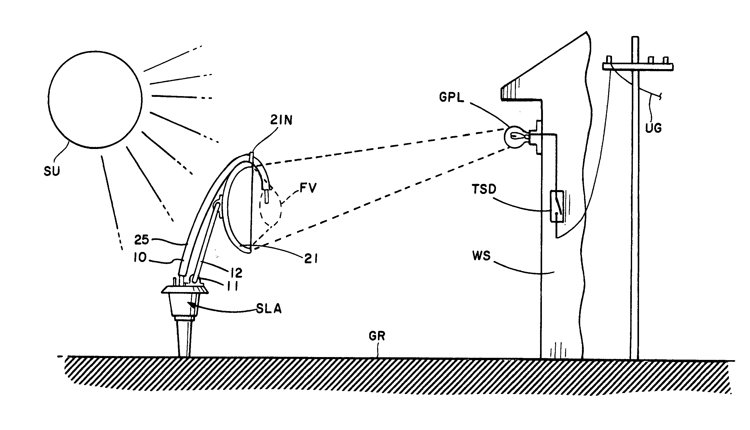
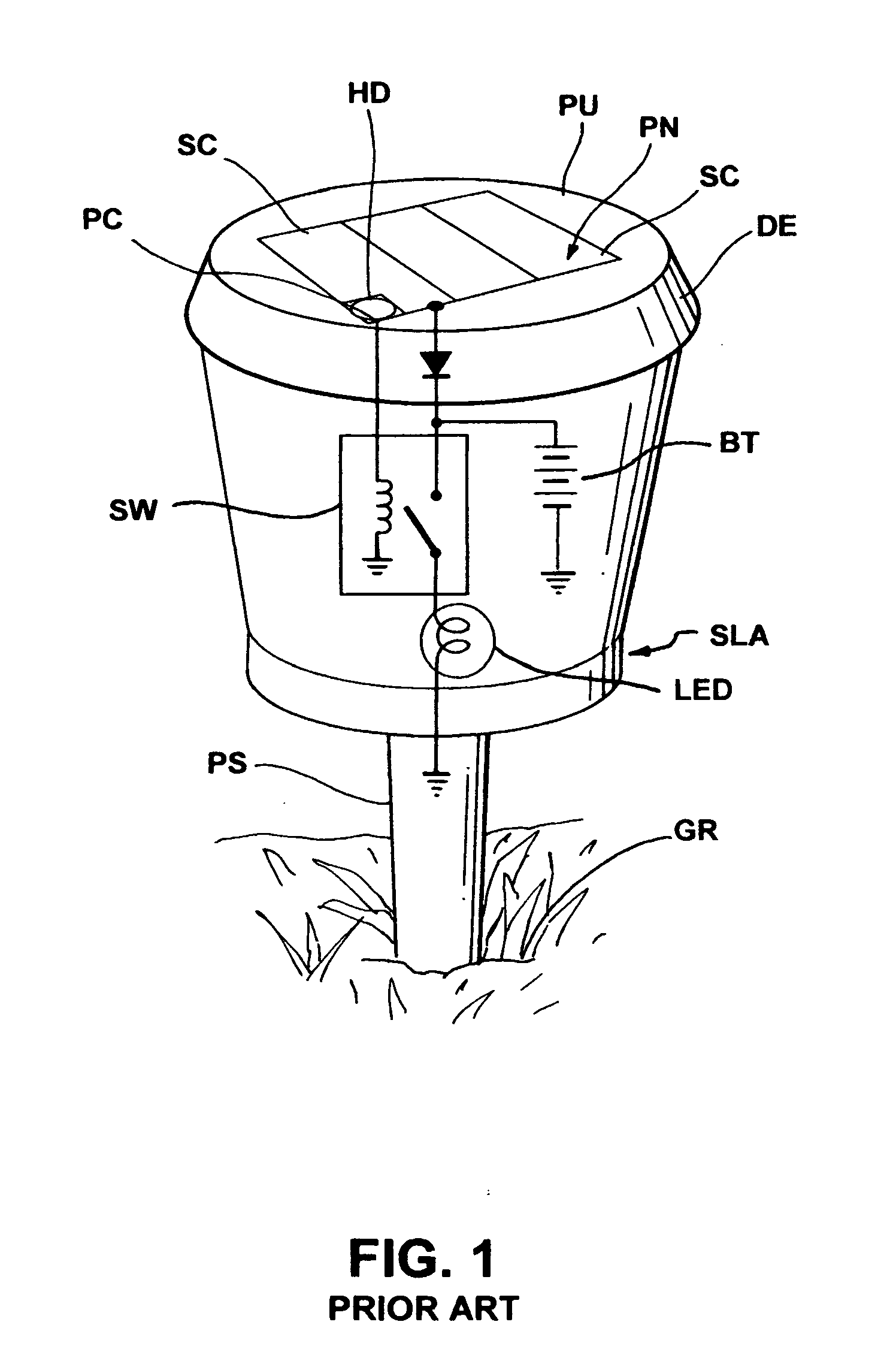
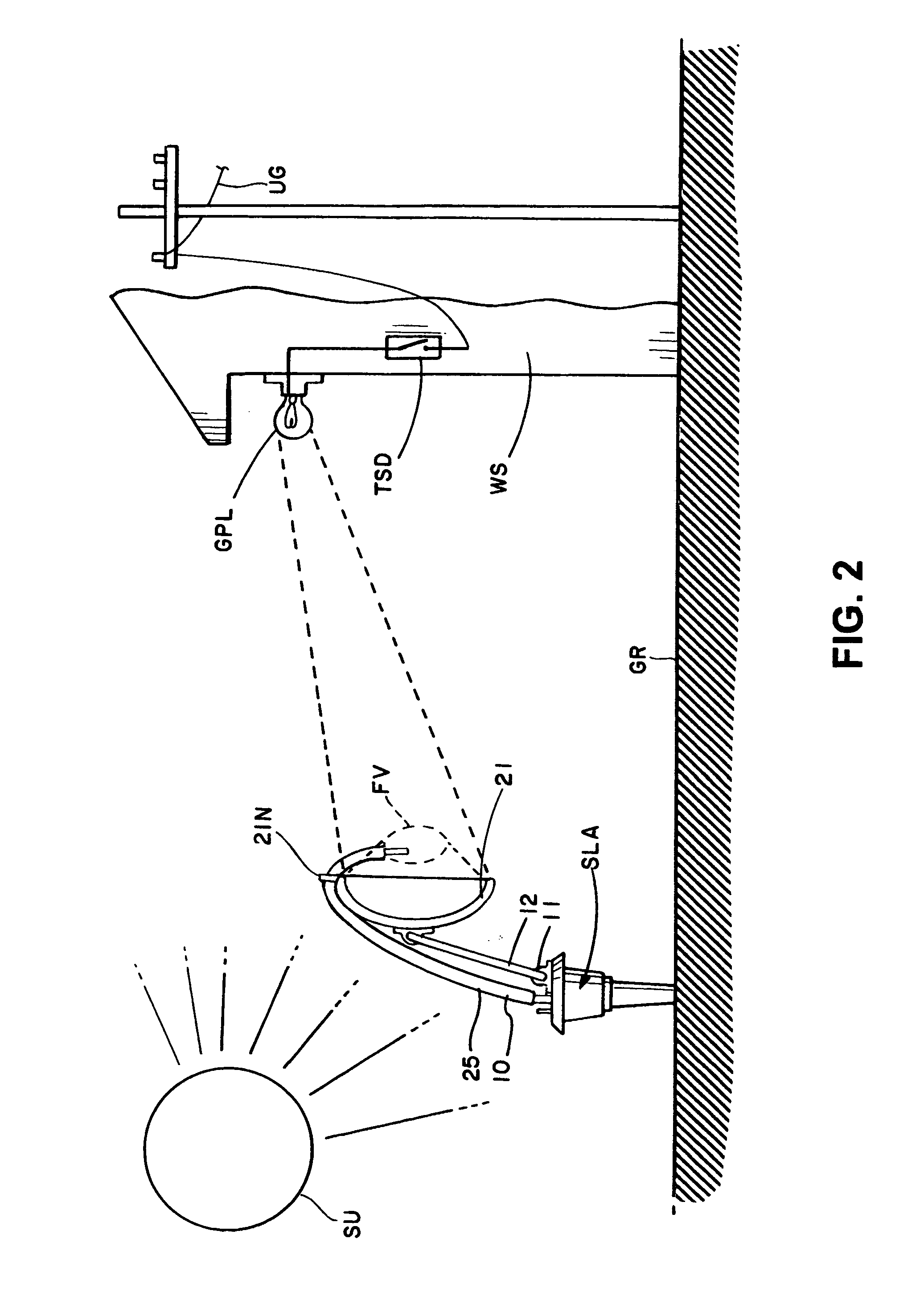
[0024]As shown in FIGS. 2 and 4 the inventive first embodiment of a light collecting device, generally designated by the numeral 10, is useful with, and is therefore generally associated with, a typical prior art solar light assembly SLA illustrated in FIG. 1 and characterized by an upper light collecting panel PU surrounded by a slanted peripheral drip edge DE and having a photovoltaic array PN mounted thereon on which one or more solar cells SC are positioned alongside a photocell PC connected to trigger a switch SW in circuit between a battery BT and a light emitting device LED. To replenish the power consumed in the course of lighting the solar cell(s) SC are also connected to the battery BT, with a blocking diode BD preventing reverse leakage. This whole solar light assembly is then mounted on a ground piercing spike PS that is pushed into the ground GR at selected locations.

[0025]A switch assembly SW in a circuit between the positive end of the battery BT and a low power light...

second embodiment

[0029]By particular reference to FIG. 4 the instant invention, generally designated by the numeral 110, includes a unitary reflector assembly 120 separately supported on its own mount comprising a length of deformable wire 112 that is inserted into the ground GR adjacent the solar light SLA. Like numbered parts functioning in a like manner to that previously described, an eccentric parabolic reflector 121 is affixed to the upper end of wire 112 and aligned to reflect the light emitted by the grid powered light GPL into a focal volume FV that is positioned to illuminate the upper panel PU including the photocell PH. To assure functional operation within the reflecting angles available reflector 121 is of a larger area than that of reflector 21 and its alignment is limited to areas where it does not interfere with the sunlight illumination of the solar light SLA. In this manner grid powered lights of various intensities may be easily accommodated in a passive arrangement that can be l...


PUM


Abstract

A sheet metal stamped light collecting reflector assembly including a generally parabolic reflector at one end of a deformable strap which at its free end is adhesively secured to the peripheral edge of a photovoltaic solar array useful to charge a storage battery connected to power a light upon the sensing an ambient light below a predetermined level for collecting sufficient light emitted by a selected grid powered light source and reflecting same to supplement said ambient light to said predetermined light level.

Description

REFERENCE TO RELATED APPLICATIONS[0001]This application is a continuation-in-part of U.S. patent application Ser. No. 13 / 987,388 filed Jul. 19, 2013, which, in turn, obtains the benefit of the earlier filing date of U.S. Provisional Application 61 / 851,247 filed on Mar. 4, 2013.STATEMENT CONCERNING GOVERNMENT INTEREST[0002]None.BACKGROUND OF THE INVENTION[0003]Field of the Invention:[0004]The present invention relates to a method and apparatus for coordinating the operation of solar charged lighting devices in response to the timed sequencing of lighting systems powered by the electrical grid, and more particularly to directionally enabled light collectors useful in photocell switching of solar charged lighting devices focused on a selected grid powered light source.[0005]Description of the Prior Art:[0006]In our current environment the use of solar lights is virtually universal, with little attention paid, however, to the over-all energy efficiencies that these very simple and troub...

Claims


Application Information

Patent Timeline
IPC IPC(8): F21S9/03F21V7/06F21V8/00F21V23/04
CPCF21S9/037G02B6/0006F21V7/06F21V23/0464F21S8/08F21V17/101F21V17/16F21W2131/10G02B6/0008Y02B20/72
Inventor ELLIS, JEREMY
Owner ELLIS JEREMY
Why Eureka
Try Eureka