
Systems and methods for calibrating scalar field contribution values for a limited number of sensors including a temperature value of an electrostatic chuck and estimating temperature distribution profiles based on calibrated values

a technology of scalar field contribution and calibration method, which is applied in the field of system and method for controlling the temperature of the electrostatic chuck in the substrate processing system, can solve the problems of unsatisfactory effects on the resulting substra

Active Publication Date: 2016-12-22
LAM RES CORP
View PDF20 Cites 10 Cited by
  • Summary
  • Abstract
  • Description
  • Claims
  • Application Information

AI Technical Summary

Benefits of technology

The patent describes a system and method for controlling the temperature of a chamber where a substrate is processed. The system includes a controller, interface, and calibration controller. The controller selects a set of fields and controls the actuators in the chamber to adjust the temperature. The interface receives feedback signals from sensors in the chamber and adjusts the control effort based on the fields. The calibration controller generates calibration values for each sensor to estimate the effect of the actuators on the substrate. The system can also include a sensor array interface to receive feedback signals from sensors in the chamber and adjust the current supplied to the thermal control elements accordingly. The technical effect of the patent is to improve the accuracy and control of the temperature in the chamber for better substrate processing.

Problems solved by technology

These temperature variations may have undesirable effects on the resulting substrates (e.g., non-uniform critical dimensions).

Method used


Image

  • Systems and methods for calibrating scalar field contribution values for a limited number of sensors including a temperature value of an electrostatic chuck and estimating temperature distribution profiles based on calibrated values
  • Systems and methods for calibrating scalar field contribution values for a limited number of sensors including a temperature value of an electrostatic chuck and estimating temperature distribution profiles based on calibrated values
  • Systems and methods for calibrating scalar field contribution values for a limited number of sensors including a temperature value of an electrostatic chuck and estimating temperature distribution profiles based on calibrated values

Examples


Embodiment Construction

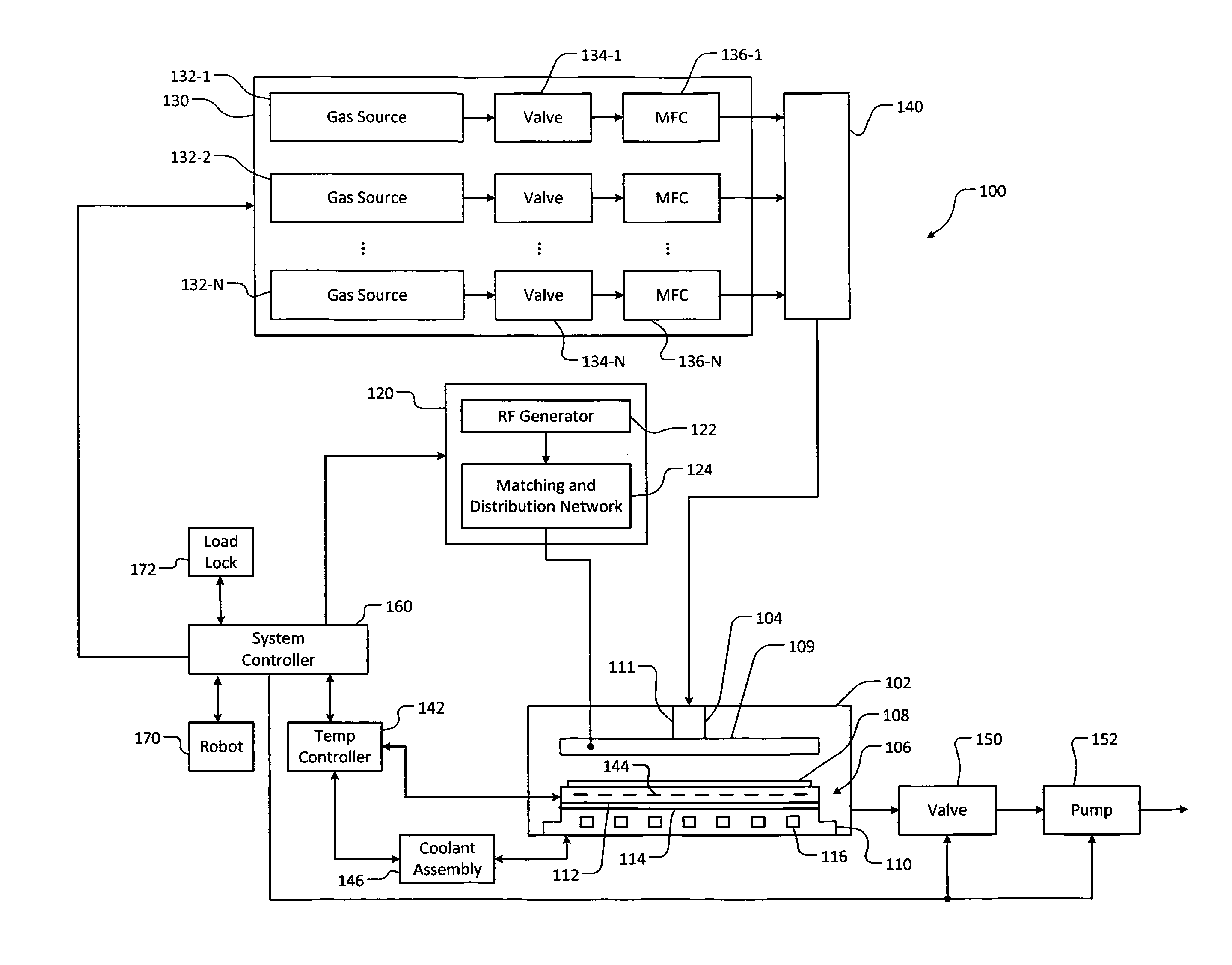
[0050]Variations in the manufacturing of heating plates can cause corresponding variations (i.e., non-uniformities) in operating characteristics of the heating plates. The variations in operating characteristics of the heating plates results in performance variations of a substrate processing system in controlling temperatures of zones of the heating plates. Characteristic variations in heating plates may include, but are not limited to, differences in thicknesses of silicone bond layers, differences in the flatness of machined surfaces, and / or differences in characteristics of TCEs within the heating plates. These non-uniformities may result in local differences in heat transfer (i.e., local temperature non-uniformity), and therefore non-uniformities in substrate temperatures. Differences can also exist between ESCs and between processing chambers. Thus, there can be a substantial amount of variability between processing a substrate in a first processing chamber with a first ESC an...


PUM


Abstract

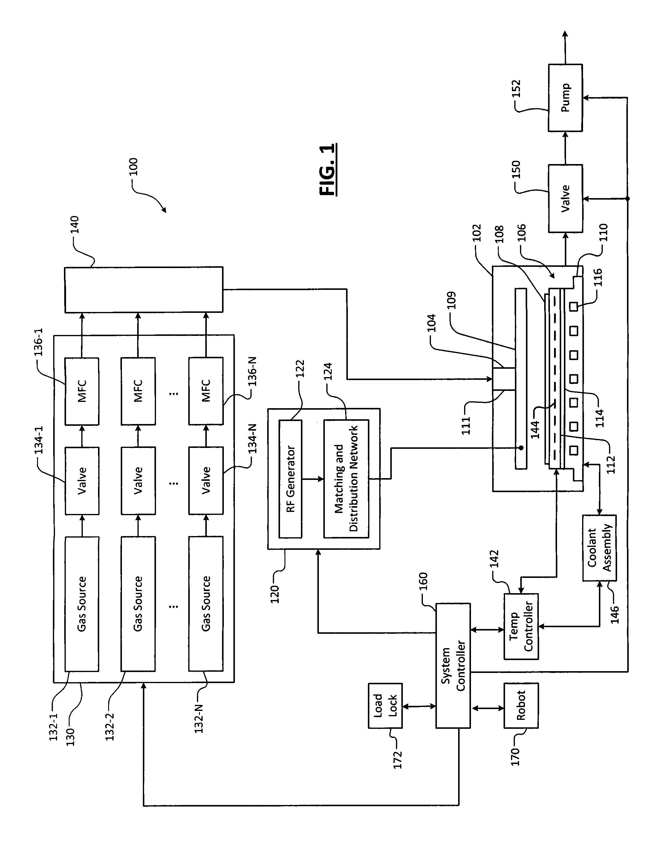
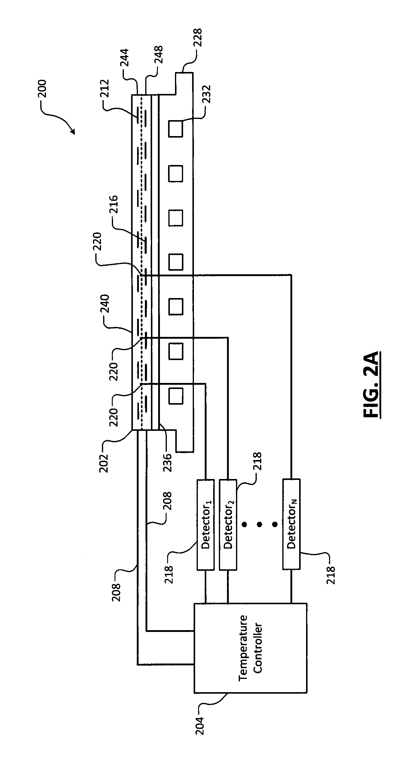
A system including a controller, an interface, and a calibration controller. The controller is configured to (i) select a set of fields, and (ii) based on the set of fields, supply control effort to first actuators in zones of a chamber. The interface is configured to receive feedback signals from sensors. The feedback signals are indicative of fields respectively of the zones. The controller is configured to adjust an amount of control effort supplied to the actuators based on the fields. The calibration controller is configured to, based on the fields, generate calibration values for each of the sensors. The calibration values for each of the sensors are indicative of field contributions corresponding respectively to the actuators.

Description

CROSS-REFERENCE TO RELATED APPLICATIONS[0001]This application claims the benefit of U.S. Provisional Application No. 62 / 182,877, filed on Jun. 22, 2015. The entire disclosure of the application referenced above is incorporated herein by reference.FIELD[0002]The present disclosure relates to substrate processing systems, and more particularly to systems and methods for controlling temperatures of an electrostatic chuck in a substrate processing system.BACKGROUND[0003]The background description provided here is for the purpose of generally presenting the context of the disclosure. Work of the presently named inventors, to the extent it is described in this background section, as well as aspects of the description that may not otherwise qualify as prior art at the time of filing, are neither expressly nor impliedly admitted as prior art against the present disclosure.[0004]Substrate processing systems may be used to perform etching, deposition, and / or other treatment of substrates such...

Claims


Application Information

Patent Timeline
IPC IPC(8): G05B19/418G01K19/00
CPCG05B19/418G05B2219/45031G01K19/00G01K3/06G01K15/005G05B2219/2602H01L21/02274H01L21/02315H01L21/324H01L21/67098H01L21/67248H01L21/6831H01L22/12H01L22/30
Inventor MUSSELMAN, MARCUSBAILEY, III, ANDREW D.
Owner LAM RES CORP
Learn More