
Audio decoder and method for providing a decoded audio information using an error concealment based on a time domain excitation signal

a time domain excitation signal and audio decoder technology, applied in the field of audio decoders for providing decoded audio information, can solve the problems of hardly being able to request a repetition of lost audio frames, data units (for example, packets) containing one or more audio frames, and avoiding artifacts and/or discontinuities, so as to improve the reliability, avoid artifacts and/or discontinuities, and improve the reliability

Active Publication Date: 2016-12-29
FRAUNHOFER GESELLSCHAFT ZUR FOERDERUNG DER ANGEWANDTEN FORSCHUNG EV
View PDF5 Cites 16 Cited by
  • Summary
  • Abstract
  • Description
  • Claims
  • Application Information

AI Technical Summary

Benefits of technology

The patent describes a method for generating decoded audio information by adding error concealment audio information to the output of an audio frame. The method uses a time domain excitation signal, which is modified to reduce the periodic component of the error concealment audio information over time and to feather out faster for signals having a shorter pitch period. The method also combines a time domain excitation signal and a noise signal to vary the percentage of the deterministic component of the input audio signal while maintaining the energy and loudness of the output signal. This allows for the modification of the time domain excitation signal without causing unacceptable audible distortions.

Problems solved by technology

However, audio contents are often transmitted over unreliable channels, which brings along the risk that data units (for example, packets) comprising one or more audio frames (for example, in the form of an encoded representation, like, for example, an encoded frequency domain representation or an encoded time domain representation) are lost.
However, this would typically bring a substantial delay, and would therefore necessitate an extensive buffering of audio frames.
In other cases, it is hardly possible to request a repetition of lost audio frames.
Accordingly, it can be avoided that signals having a shorter length of the pitch period are repeated too often with high intensity, because this would typically result in an unnatural hearing impression.

Method used


Image

  • Audio decoder and method for providing a decoded audio information using an error concealment based on a time domain excitation signal
  • Audio decoder and method for providing a decoded audio information using an error concealment based on a time domain excitation signal
  • Audio decoder and method for providing a decoded audio information using an error concealment based on a time domain excitation signal

Examples


Embodiment Construction

1. Audio Decoder According to FIG. 1

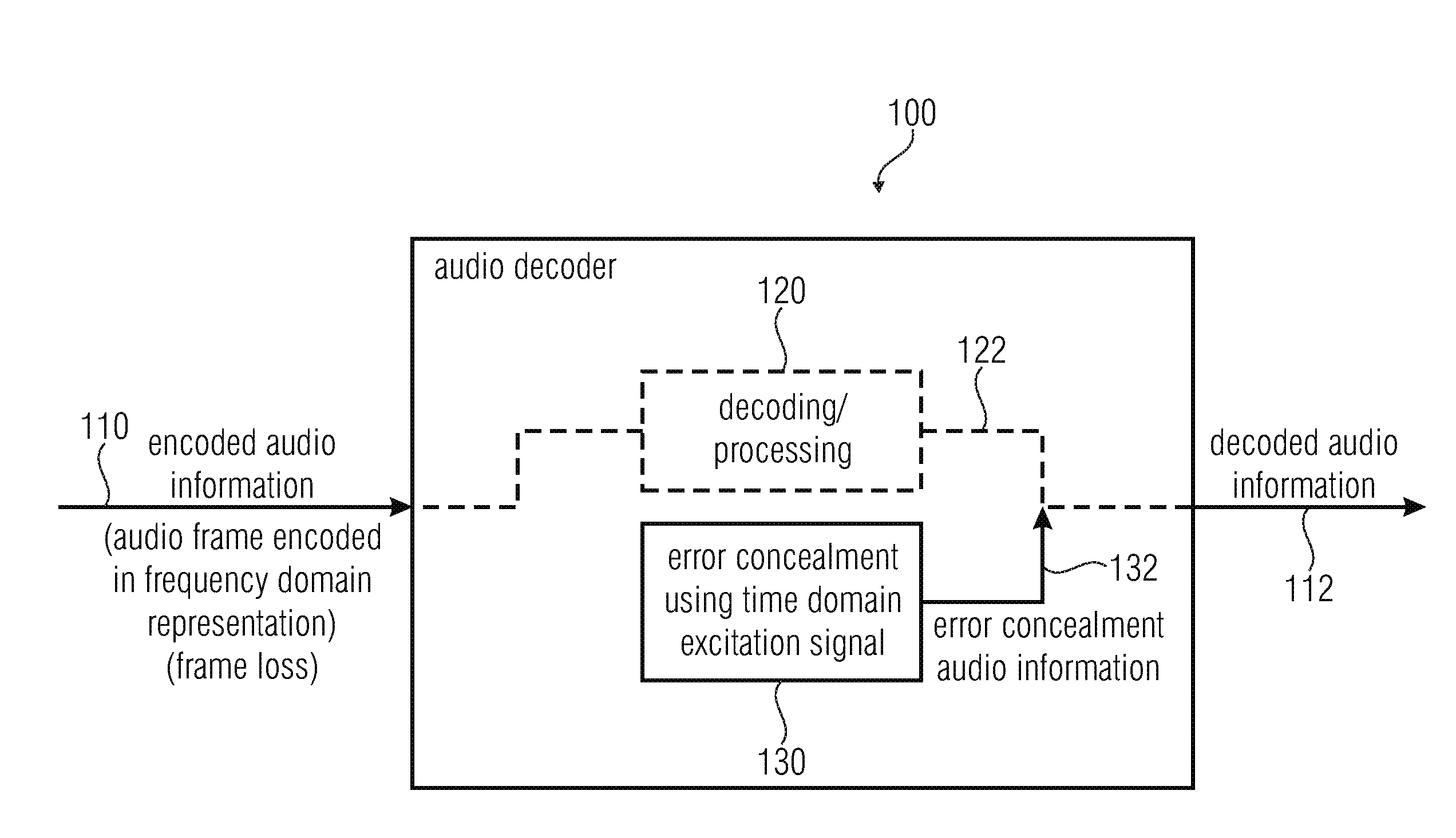
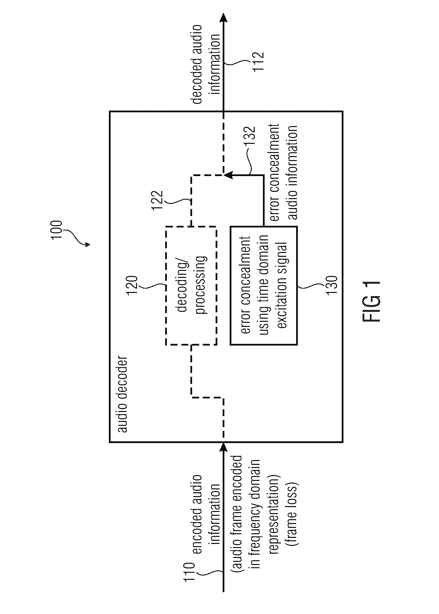
[0141]FIG. 1 shows a block schematic diagram of an audio decoder 100, according to an embodiment of the present invention. The audio decoder 100 receives an encoded audio information 110, which may, for example, comprise an audio frame encoded in a frequency-domain representation. The encoded audio information may, for example, be received via an unreliable channel, such that a frame loss occurs from time to time. The audio decoder 100 further provides, on the basis of the encoded audio information 110, the decoded audio information 112.

[0142]The audio decoder 100 may comprise a decoding / processing 120, which provides the decoded audio information on the basis of the encoded audio information in the absence of a frame loss.

[0143]The audio decoder 100 further comprises an error concealment 130, which provides an error concealment audio information. The error concealment 130 is configured to provide the error concealment audio information 132 for co...


PUM


Abstract

An audio decoder for providing a decoded audio information on the basis of an encoded audio information includes an error concealment configured to provide an error concealment audio information for concealing a loss of an audio frame following an audio frame encoded in a frequency domain representation using a time domain excitation signal.

Description

CROSS-REFERENCE TO RELATED APPLICATIONS[0001]This application is a continuation of U.S. application Ser. No. 15 / 142,547, filed Apr. 29, 2016 which is a continuation of International Application No. PCT / EP2014 / 073035, filed Oct. 27, 2014, and additionally claims priority from European Applications Nos. EP13191133, filed Oct. 31, 2013, and EP14178824, filed Jul. 28, 2014, all of which are incorporated herein by reference in their entirety.BACKGROUND OF THE INVENTION[0002]Embodiments according to the invention create audio decoders for providing a decoded audio information on the basis of an encoded audio information.[0003]Some embodiments according to the invention create methods for providing a decoded audio information on the basis of an encoded audio information.[0004]Some embodiments according to the invention create computer programs for performing one of said methods.[0005]Some embodiments according to the invention are related to a time domain concealment for a transform domain...

Claims


Application Information

Patent Timeline
Patent Type & Authority Applications(United States)
IPC IPC(8): G10L19/005G10L19/09G10L19/125
CPCG10L19/005G10L2019/0011G10L19/09G10L19/125G10L19/02G10L19/08G10L19/008G10L19/0212G10L19/04G10L25/90
Inventor LECOMTE, JEREMIEMARKOVIC, GORANSCHNABEL, MICHAELPIETRZYK, GRZEGORZ
Owner FRAUNHOFER GESELLSCHAFT ZUR FOERDERUNG DER ANGEWANDTEN FORSCHUNG EV
Learn More