Eureka AIR delivers breakthrough ideas for toughest innovation challenges, trusted by R&D personnel around the world.

Method for adhering parts and device for implementing said method

a technology of adhesive layer and parts, applied in the direction of machines/engines, other domestic articles, liquid fuel engines, etc., can solve the problems of reducing the mechanical properties of parts obtained by using the solution, imposing constant pressure together with a rise in temperature on the adhesive layer having a complex three-dimensional shape, and reducing the duration and cost of the method

Active Publication Date: 2017-01-05
SN DETUDE & DE CONSTR DE MOTEURS DAVIATION S N E C M A
View PDF1 Cites 1 Cited by
  • Summary
  • Abstract
  • Description
  • Claims
  • Application Information

AI Technical Summary

Benefits of technology

The patent text describes a method for bonding parts together using a liquid applied through a wall. The device used ensures that the liquid is applied against the wall without changing the shape of the inside face of the wall. This results in a constant pressure being applied to the adhesive, regardless of the shape of the parts being bonded together. The device also generates sufficient pressure on the wall to move it and reduce the size of the chamber. The technical effect of the method is improved bonding efficiency and strength between the parts.

Problems solved by technology

Adhesively bonding a metal leading edge on a turbine engine blade made of composite material is a technical operation that can be relatively complex.
Imposing a constant pressure together with a rise in temperature on an adhesive layer having a complex three-dimensional shape can be relatively difficult to achieve.
Nevertheless, the parts obtained by using that solution may fail to have satisfactory mechanical properties.
The same difficulties can be encountered when adhesively bonding other types of part, such as for example:bonding a metal leading or trailing edge on an outlet guide vane;bonding metal hollow outlet guide vanes; or bonding metal reinforcing sectors on flanges of an axisymmetric casing made of composite material.

Method used


Image

  • Method for adhering parts and device for implementing said method
  • Method for adhering parts and device for implementing said method
  • Method for adhering parts and device for implementing said method

Examples


example

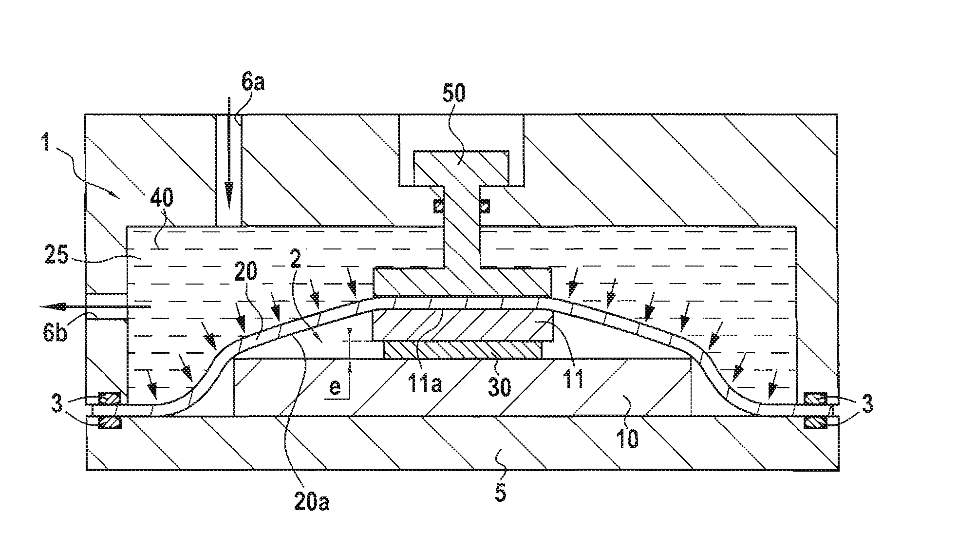
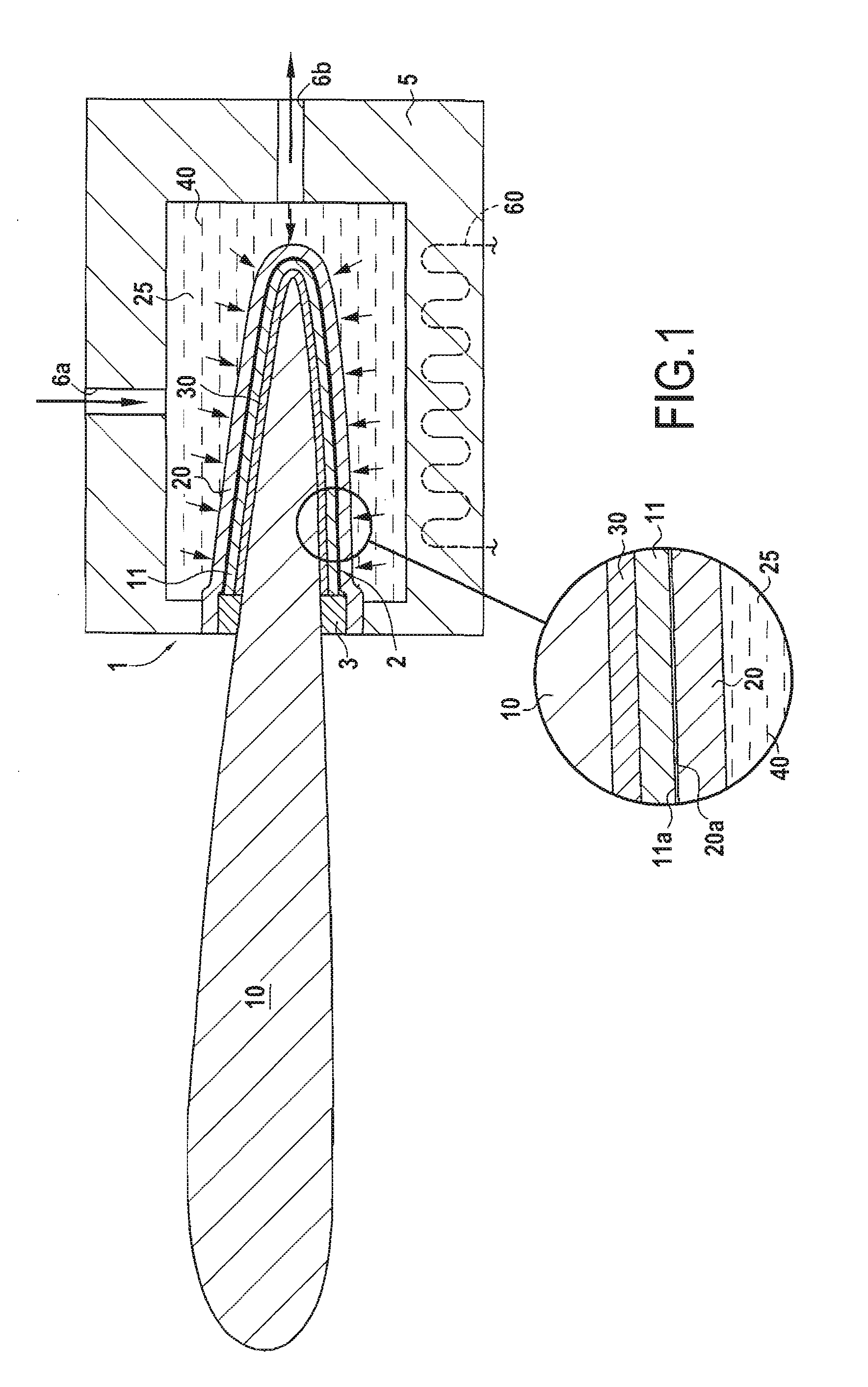
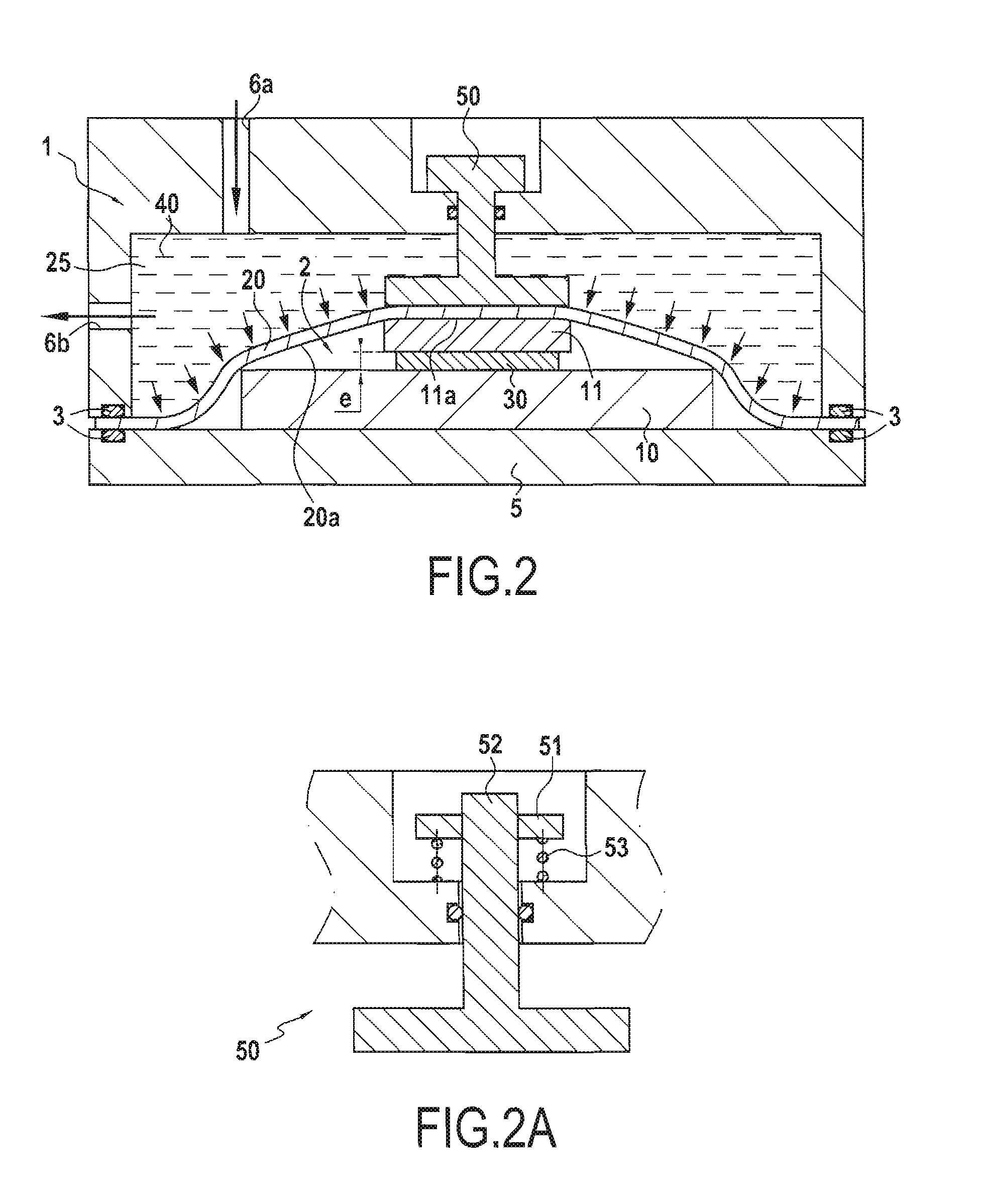
[0131]There follows an operating protocol for bonding a titanium leading edge onto a composite material blade comprising carbon fiber reinforcement densified by a PR520 epoxy resin, the bonding being performed within tooling made of steel.

[0132]The leading edge, the film of epoxy adhesive, and the blade are initially assembled together.

[0133]The resulting assembly is placed in a chamber defined by a shaped silicone membrane.

[0134]The assembly is heated to 160° C. and oil is applied against the membrane. The applied oil serves to exert a pressure of 3 bars and to enable the membrane to bear against the leading edge.

[0135]The assembly as put under pressure in this way is subjected to a temperature of 180° C. for 2 hours in order to bond the leading edge to the blade.

[0136]The term “comprising / containing a” should be understood as “comprising / containing at least one”.

[0137]The term “lying in the range . . . to . . . ” should be understood as including the limits.


PUM

PropertyMeasurementUnit
Fractionaaaaaaaaaa
Pressureaaaaaaaaaa
Volumeaaaaaaaaaa

Abstract

A method is provided of bonding together at least two parts. The method includes assembling together at least two parts and at least one adhesive layer, the adhesive being configured so that its adhesive power increases on heating as a result of it polymerizing, at least one of the parts being made of composite material or of metal, the adhesive layer being present, after assembly, between the parts, the assembled together parts and the adhesive being present in a chamber defined by a wall, the wall having an inside face situated facing a first part present between the adhesive layer and the wall, the first part being intended to be bonded to a second part and only a fraction of the second part being present inside the chamber; and applying a liquid against the wall on its side opposite from the chamber.

Description

BACKGROUND OF THE INVENTION[0001]The invention relates to methods of adhesively bonding parts together and to devices for performing the method.[0002]Adhesively bonding a metal leading edge on a turbine engine blade made of composite material is a technical operation that can be relatively complex. Such bonding may involve an operation of placing the layer of adhesive between the two substrates, and raising temperature, while also applying pressure to condition the adhesive layer correctly. It may also be necessary to maintain both the temperature and the pressure for a certain length of time that is sufficient to polymerize the material used in the adhesive layer.[0003]Imposing a constant pressure together with a rise in temperature on an adhesive layer having a complex three-dimensional shape can be relatively difficult to achieve.[0004]One solution for solving this problem is to make special molds in which the thickness of the adhesive layer is not constant. Nevertheless, the par...

Claims


Application Information

Patent Timeline
IPC IPC(8): B29C65/48F01D5/28F16B11/00B29C65/00
CPCB29C65/48B29C66/532B29C66/721F05D2300/603F16B11/006B29L2031/08F05D2230/23F01D5/282B29C65/18B29C65/26B29C66/1122B29C66/301B29C66/742B29C66/81459F04D29/324F01D5/147F01D5/288F04D29/023B29C65/4835Y10T156/103Y10T156/1002Y10T156/1031B29C70/84B29C70/72B29C65/4815B29C65/70B29C65/026B29C65/02
Inventor GODON, THIERRYSCHNEIDER, JULIENVARIN, FRANCK
Owner SN DETUDE & DE CONSTR DE MOTEURS DAVIATION S N E C M A
Why Eureka
Eureka Blog
Learn More