
Cable Tension Monitor

a technology of tension monitor and cable, which is applied in the direction of power supply, door/window fitting, construction, etc., can solve the problems of slow door speed, slack often occurring, and cable unspooling (or “jumping”) from the drum, and achieves the effect of high flexibility in practice and easy deploymen

Active Publication Date: 2017-01-05
THE CHAMBERLAIN GRP INC
View PDF8 Cites 4 Cited by
  • Summary
  • Abstract
  • Description
  • Claims
  • Application Information

AI Technical Summary

Benefits of technology

The patent describes a system for detecting a lack of tension in the cables used in movable barrier settings and alerting the operator to stop or reverse the movement of the barrier. This system can work with a range of sensors and operators with minimal modification to the existing equipment. Overall, the system provides a flexible and adaptable solution to improve the operational safety and reliability of movable barriers.

Problems solved by technology

However, various events can cause slack in a cable, resulting in the cable unspooling (or “jumping”) from the drum.
For example, slack often occurs when the speed of the door is slower than that of the operator.
This slowdown in the movement of the door often can be attributed to obstructions in the path of the door.
Abnormalities along the surface of the drum or guide track can also cause slack in the cable.
Slack in cables of movable barrier systems is particularly problematic.
An unspooled (or “thrown”) cable can become entangled or fall from the drum, rendering the counterbalance system inoperative.
Slack in a cable may also result in uncontrolled downward acceleration of the door when, for example, an obstacle previously obstructing downward movement of the door is removed.
Resetting of thrown cables is time consuming and expensive, resulting in downtime and often necessitating a service call from a trained technician.
Because cables are typically abrasive (having been typically formed of multi-strand steel), this contact damages the detection devices over time.

Method used


Image

  • Cable Tension Monitor
  • Cable Tension Monitor
  • Cable Tension Monitor

Examples


Embodiment Construction

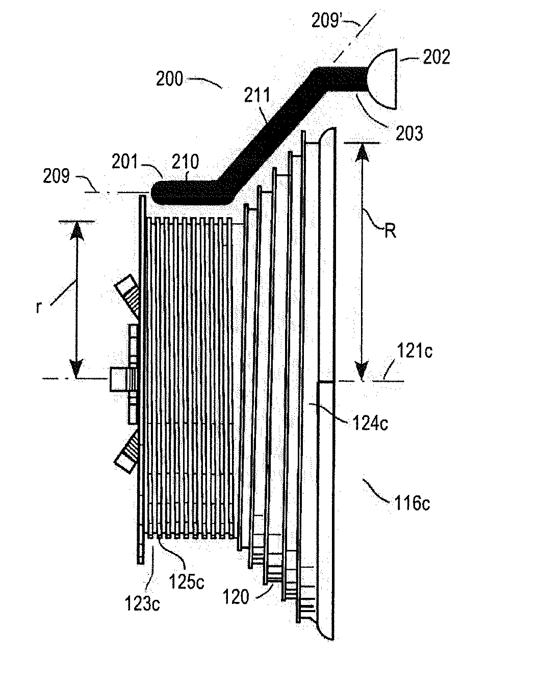
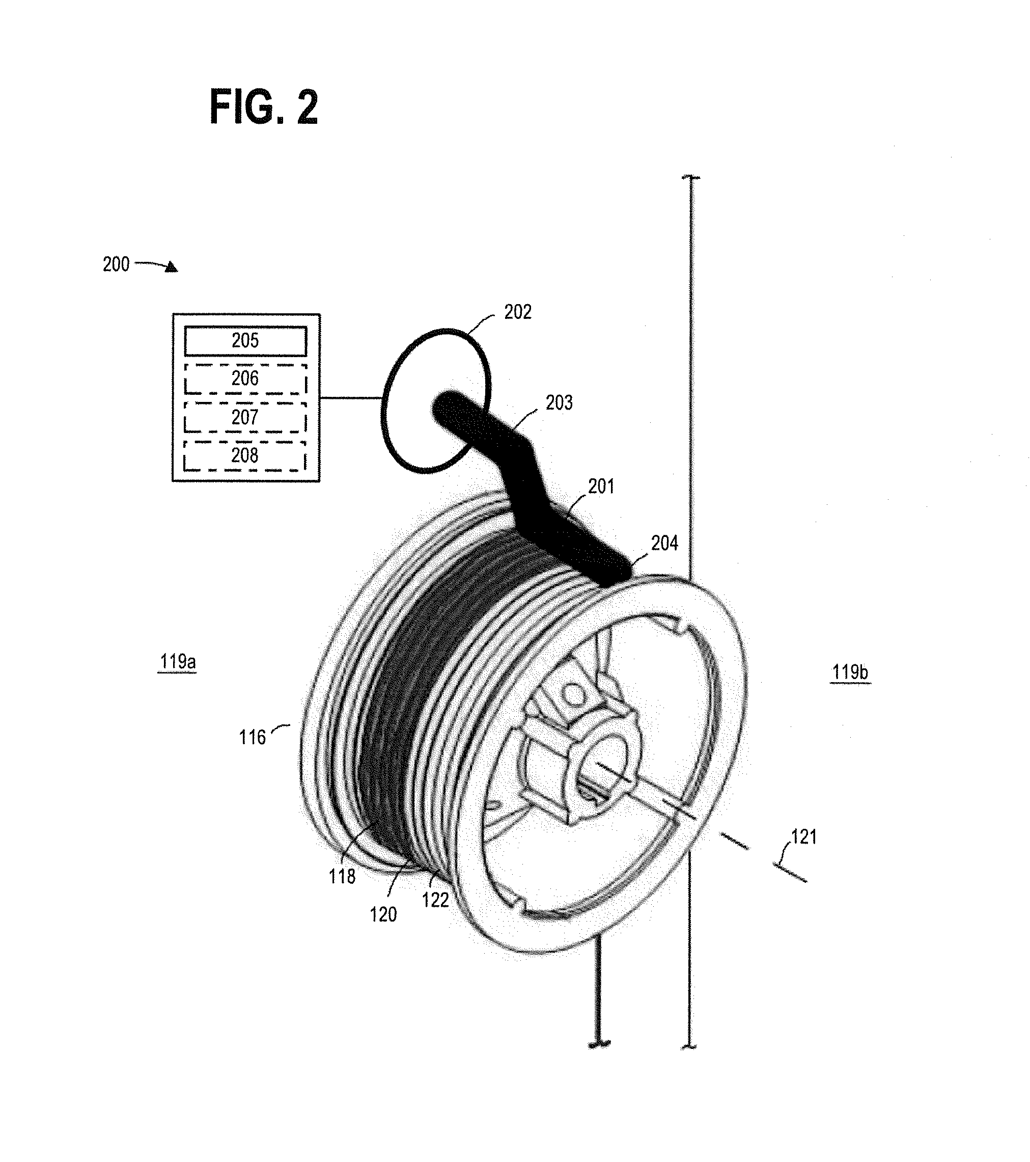
[0020]Generally speaking and pursuant to these various embodiments, a sensor apparatus is provided for a movable barrier operator having a rotatable drum configured to wind up and pay out an elongate member to at least support corresponding movement of a movable barrier connected to the elongate member.

[0021]Referring to the drawings, it may be helpful to first describe an illustrative application setting. It will be understood that the specifics of this example are intended to serve only in an illustrative regard and are not intended to express or suggest any corresponding limitations with respect to the scope of these teachings

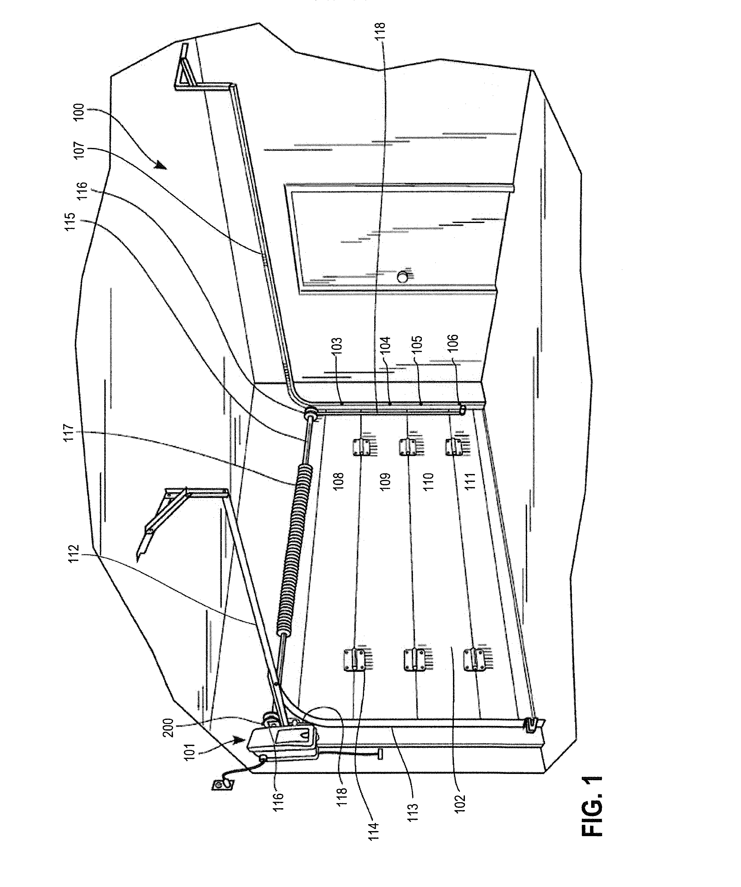
[0022]In the illustrative example shown in FIG. 1, a movable barrier system 100 comprises, in part, a movable barrier operator 101 positioned within a garage. The movable barrier operator 101 serves to control and effect selective movement of a multipanel garage door 102. The movable barrier operator 101 includes a motor (not shown) to provide motion to the ...


PUM


Abstract

A sensor apparatus for a movable barrier system having a rotatable drum and an elongate member that winds up on and pays out from an external surface of the rotatable drum. The sensor apparatus includes a base portion, a sensing portion, and a controller. The sensing portion senses a first spaced apart proximity of the elongate member relative to the sensing portion and a second spaced apart proximity of the elongate member relative to the sensing portion. The controller detects a change in the proximity of the elongate member relative to the sensing portion without the elongate member contacting the sensing portion.

Description

TECHNICAL FIELD[0001]The present disclosure generally relates to monitoring tension in an elongate member such as a cable. More specifically, the present disclosure relates to monitoring cable tension in movable barrier settings.BACKGROUND[0002]Movable barrier systems typically include an operator that selectively moves a movable barrier (such as a segmented or one-piece garage door, swinging gate, sliding gate, rolling shutter, and so forth) between an opened and a closed position along guide tracks. Such barrier systems often include a counterbalance system, typically either a torsion spring counterbalance system or an extension spring counterbalance system.[0003]A torsion spring counterbalance system includes a shaft (sometimes referred to as a jack shaft or torsion shaft), one or more torsion springs coiled around and connected to the shaft, and one or more drums connected to the shaft. Associated with each drum is a cable attached at one end to the drum (typically at a notch or...

Claims


Application Information

Patent Timeline
Patent Type & Authority Applications(United States)
IPC IPC(8): E05F15/41B65H75/44
CPCE05Y2900/106E05D13/1261E05D13/1269E05D15/24E05Y2201/654E05Y2201/664E05Y2201/672E05Y2400/44E05Y2400/502E05F15/686B65H75/4484
Inventor LAIRD, EDWARD THOMASOLMSTED, ROBERT JOHN
Owner THE CHAMBERLAIN GRP INC
Learn More