
Silent wire harness press fitting machine

A silent wire and beam pressure technology, applied in metal processing, metal processing equipment, manufacturing tools, etc., can solve the problems of low work efficiency, affect work efficiency, and no protective cover is installed, and achieve the effect of quick placement and improved work efficiency.

Inactive Publication Date: 2019-07-23
SHIYAN BANGWEI IND & TRADE
View PDF1 Cites 2 Cited by
  • Summary
  • Abstract
  • Description
  • Claims
  • Application Information

AI Technical Summary

Problems solved by technology

[0004] Based on the retrieval of the patent application number: CN201820160173.3, although the application can adjust the position of the placement seat through the screw rod to improve flexibility, there are still the following deficiencies: one is that the work efficiency is low, and the above application does not have Set the corresponding limit structure, such as the limit structure when placing the terminal, then you first need to adjust the position of the terminal to align the indenter when placing the terminal, the whole process is a waste of time and affects work efficiency; moreover, the practicability is low , the crimping wire structure in the above application is a fixed type, which cannot be well adapted to wire harnesses of different diameters, and when compressing a wire harness with a larger diameter, it is easy to cause damage to the surface of the wire harness; finally, the protection is weak, The above application is not equipped with a protective cover, and the terminal jumps out during the work process, which may easily cause injury to the staff

Method used

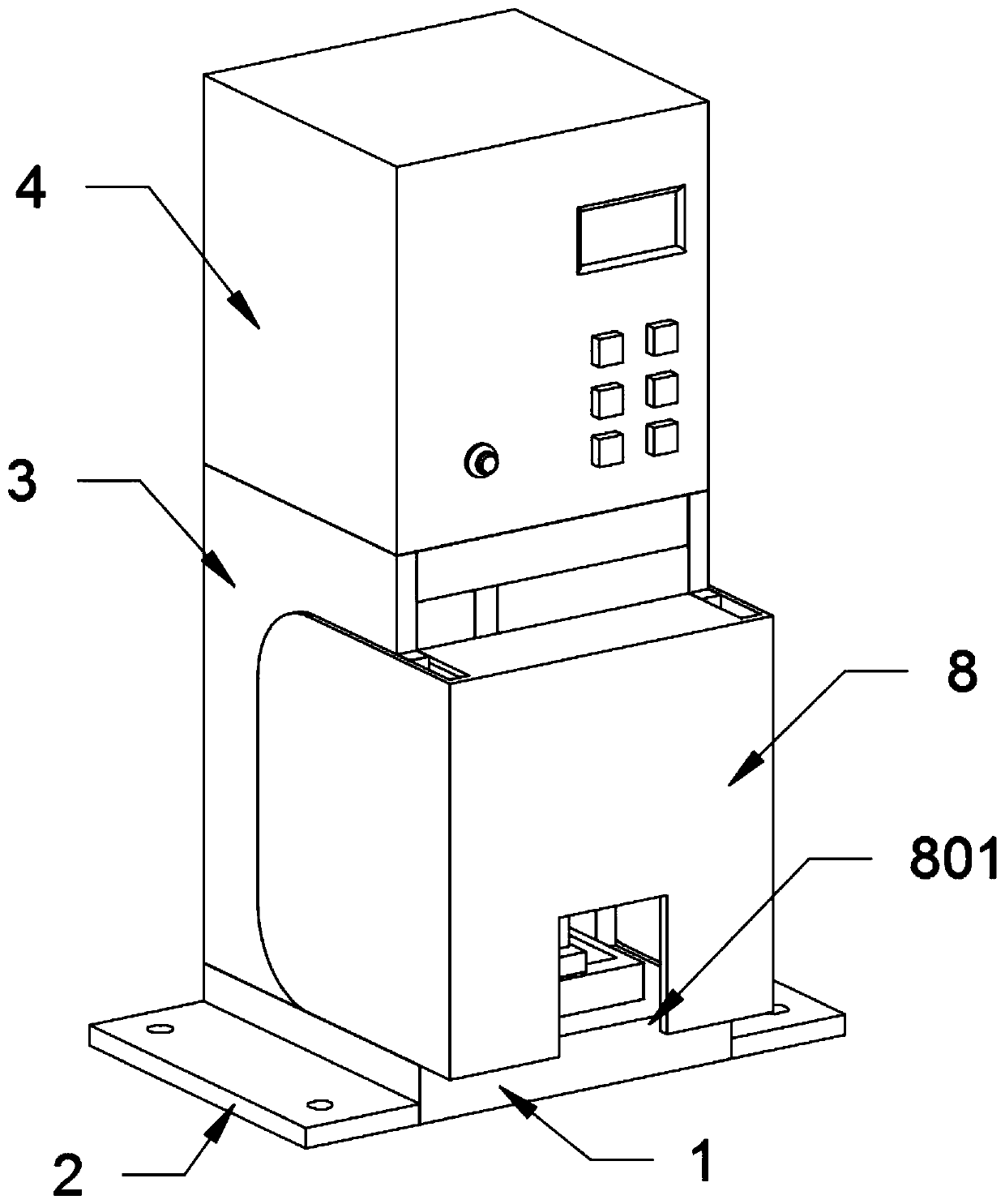
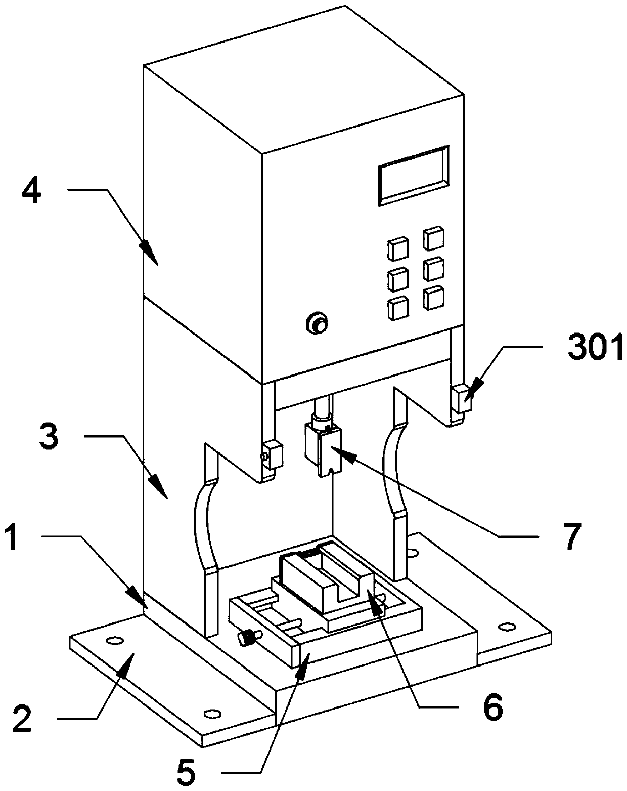
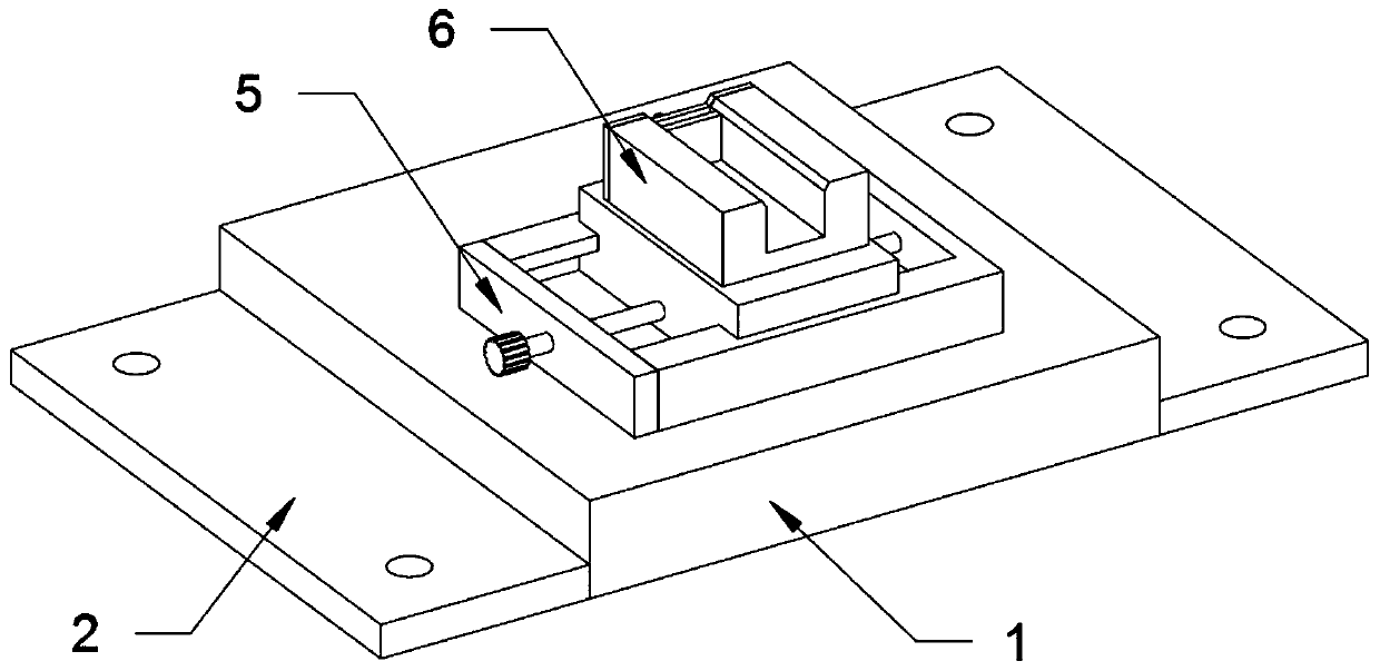

Image

  • Silent wire harness press fitting machine
  • Silent wire harness press fitting machine
  • Silent wire harness press fitting machine

Examples


Embodiment

[0032] as attached figure 1 to attach Figure 7 Shown:

[0033]The present invention provides a silent wire harness pressing machine, which includes a base 1, a fixed plate 2, a support plate 3, a rotating connection seat 301, a press machine main body 4, an adjusting seat structure 5, a sliding seat 501, a sliding block 502, an adjusting screw A503, a press Seat structure 6, concave seat 601, cover plate 602, block 603, adjustment screw B604, pressure head structure 7, pressure head body 701, wire harness fixing plate 702, wire harness fixing groove 70201, sliding plate 70202, rectangular plate 703, Cylindrical rod 704, spring 705, protective cover 8 and rectangular groove 801; Described base 1 is a rectangular structure, and described base 1 left end face and right end face are all welded with a fixing plate 2; Described base 1 top end face left side and A support plate 3 is welded on the right side of the top surface, and a press-fitting machine main body 4 is welded on t...


PUM


Abstract

The invention provides a silent wire harness press fitting machine comprising a base, a protective cover and a rectangular groove. The base is of a rectangular structure, and the left end surface andthe right end surface of the base are each provided with a fixing plate in a welded manner; a telescopic shaft of a main body of the press fitting machine is in fixed connection with a pressing head structure, and the pressing head structure is composed of a pressing head body, wire harness fixing plates, a rectangular plate, a cylindrical rod and a spring; the rectangular plate is welded to the front side of the pressing head body, and the cylindrical rod is welded to the bottom end face of the rectangular plate. Due to the arrangement of a concave seat, a cover plate and a stopping block, onone hand, the stopping block is arranged to serve as a limit plate for terminal containing, and the front and rear positions of a terminal are adjusted when the head of the terminal is in contact with the stopping block; and on the other hand, the front and rear positions of the stopping block is adjusted so that terminals in different sizes can be limited. Compared with the prior art, the devicecan conduct limiting when the terminal is placed, placement is relatively quick, and the work efficiency can be improved.

Description

technical field [0001] The invention belongs to the technical field of mechanical equipment, and more specifically relates to a silent wire harness pressing machine. Background technique [0002] The silent terminal machine refers to a machine used in wire processing, which can press the metal head to the wire end. Then conduct the conduction. The terminals produced by the silent terminal machine are usually for more convenient connection. The two wires can be connected together stably without soldering, and only need to be unplugged when dismantling. The ultra-quiet terminal machine adopts modern frequency converter control technology. It is developed for the common terminal dies at home and abroad. It is suitable for crimping various terminals and wires. Digital control, safety protection system, and simple operation achieve mechanical The accuracy, strength and safety of the terminal machine make the terminal machine run ultra-quietly, and the frequency converter itself ...

Claims


Application Information

Patent Timeline
Patent Type & Authority Applications(China)
IPC IPC(8): B23P19/027
CPCB23P19/027
Inventor 汪永诚
Owner SHIYAN BANGWEI IND & TRADE
Learn More