Rotor blade or guide vane assembly

a technology of guiding vane and turbine blade, which is applied in the direction of machines/engines, stators, mechanical equipment, etc., can solve the problems that the rotational speed of the turbine has a significant impact on loading

Inactive Publication Date: 2017-01-05
ANSALDO ENERGIA IP UK LTD
View PDF11 Cites 5 Cited by
  • Summary
  • Abstract
  • Description
  • Claims
  • Application Information

AI Technical Summary

Benefits of technology

[0014]The technical problem solved by the present invention relates to joining an outer shell to an inner core structure of an airfoil of a rotor blade or a guide vane of a turbomachine, especially a gas turbine. In addition, the present invention solves the problem of assembling or disassembling such a rotor blade or guide vane.

Problems solved by technology

Obviously, the rotational speed of the turbine has a significant impact on the loadings.

Method used


Image

  • Rotor blade or guide vane assembly
  • Rotor blade or guide vane assembly
  • Rotor blade or guide vane assembly

Examples


Embodiment Construction

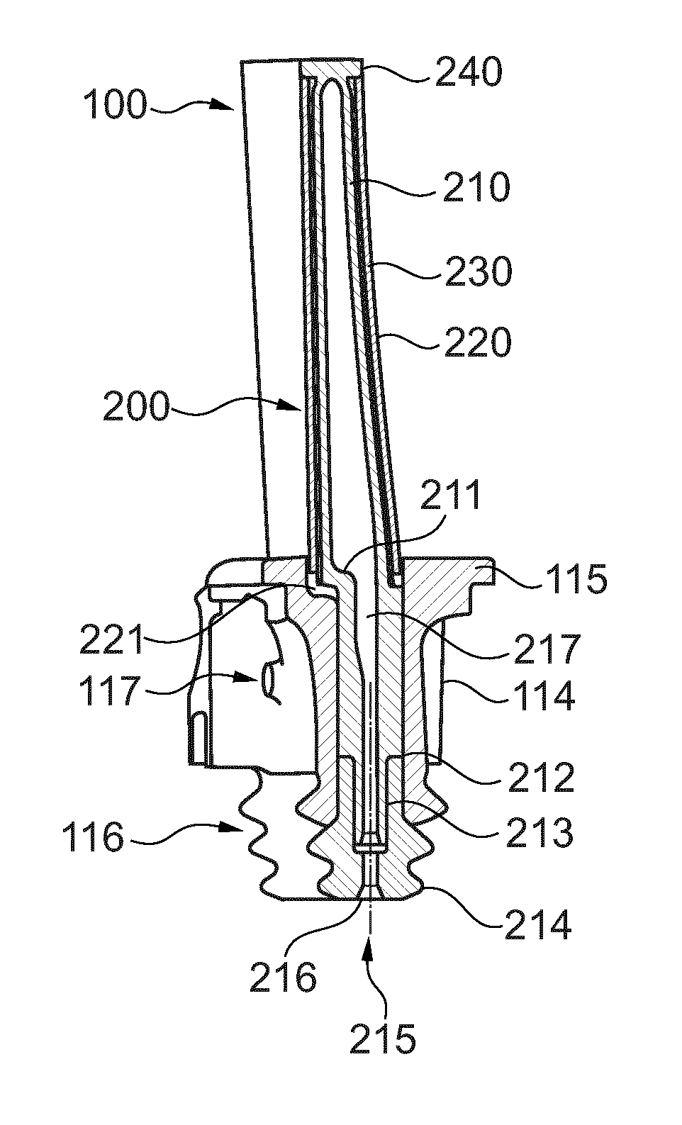
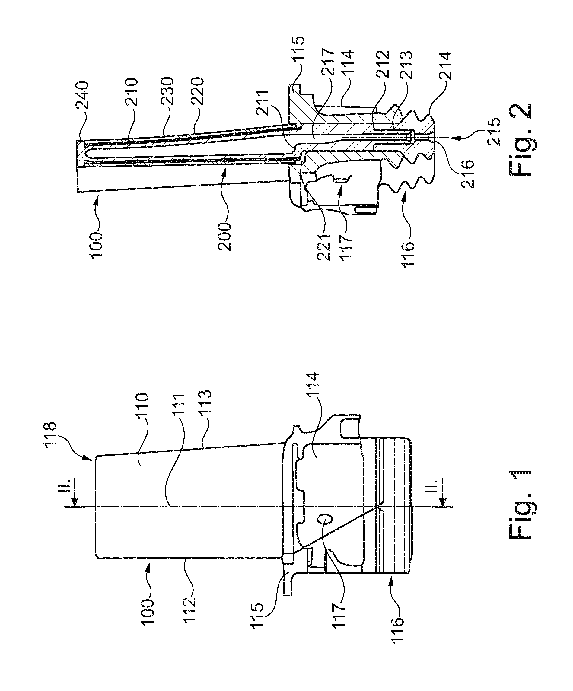
[0098]In FIG. 1 a rotor blade 100 according to an exemplary embodiment of the invention is reproduced. The rotor blade 100 comprises a blade airfoil 110 which extends in the longitudinal direction of the rotor blade along a longitudinal axis 111. The blade airfoil 110, which is delimited by a leading edge 112 and a trailing edge 113 in the flow direction, merges into a shank 114 at the lower end beneath an inner platform 115 which forms the inner wall of the hot gas passage, the shank ends in a blade root 116 with a so called fir-tree-shaped cross-sectional profile by which the blade 100 can be fastened on a blade carrier, especially on a rotor disk, by inserting into a corresponding axial slot.

[0099]The inner platform abuts the platforms of neighbouring blades to define a gas passage inner wall for the turbine. An outer not shown thermal shield at the tip of the blade airfoil 118 cooperates again with its neighbours in the manner shown to define the outer wall of the turbine's gas ...


PUM

PropertyMeasurementUnit
thicknessaaaaaaaaaa
thicknessaaaaaaaaaa
thicknessaaaaaaaaaa

Abstract

The disclosure refers to a method of assembling or disassembling a rotor blade or guide vane assembly, wherein the rotor blade or guide vane includes an airfoil and additional structured peripheral members forming at least an inner and/or an outer platform of the rotor blade or guide vane. The airfoil includes at least one airfoil sub-structure designed for anchoring at least one superposed component for the purpose of a thermal protection. The connection between the airfoil sub-structure and the superposed component is supported on friction-locked device, wherein the airfoil sub-structure is formed by a spar and the superposed component includes at least one flow-charged outer shell. Connection between the spar or airfoil understructure and flow-charged outer shell is formed by a force-fit and/or a form-fit fixation or a shrinking joint, wherein the airfoil and additional structured peripheral members is formed by friction-locked device with a detachable, permanent or semi-permanent fixation.

Description

TECHNICAL FIELD[0001]The present invention relates to a rotor blade or guide vane assembly of a turbomachine, especially of a gas turbine engine. In particular, the invention relates to a modularly designed blade or vane of a turbomachine with one or more interchangeable elements or modules. In addition, the invention is applicable for other turbomachine parts, like heat shields, inner platform, outer platform, airfoil carrier, etc.[0002]Additionally, the invention relates to manufacturing, reconditioning, joining and disassembling methods with respect to turbomachine components.BACKGROUND OF THE INVENTION[0003]EP 2 204 537 A2 discloses a guide vane for a gas turbine. This vane consists of a composite airfoil structure. The composite airfoil structure may have an opening. The vane may include a spar. The spar may have a body, which may be disposed within the opening. A standoff structure may be disposed within the opening. In some nonlimiting embodiments, a cooling air gap may be de...

Claims


Application Information

Patent Timeline
Patent Type & Authority Applications(United States)
IPC IPC(8): F01D5/14F01D5/28F01D9/04F01D5/18
CPCB23P11/025F01D5/147F01D5/18F01D5/28F01D9/02F05D2240/80F05D2230/60F05D2230/51F01D5/187F01D5/282F01D5/288F01D9/041F05D2230/10F05D2230/21F05D2230/40F05D2240/12F05D2240/30F05D2260/20F05D2300/20F05D2300/6032F05D2300/6033F05D2300/611
Inventor OPDERBECKE, THOMASHOEVEL, SIMONEFERBER, JOERGEN
Owner ANSALDO ENERGIA IP UK LTD
Why Eureka
Try Eureka