Eureka AIR delivers breakthrough ideas for toughest innovation challenges, trusted by R&D personnel around the world.

Device, program, recording medium, and method for extending service life of memory

Inactive Publication Date: 2017-01-05
FIXSTARS SOLUTIONS
View PDF1 Cites 1 Cited by
  • Summary
  • Abstract
  • Description
  • Claims
  • Application Information

AI Technical Summary

Benefits of technology

The invention aims to prevent the performance of a system from decreasing due to data rewriting being concentrated in specific memories. It assigns data rewrite processing or processing involving data rewriting to multiple devices based on the number of times data rewriting has occurred in a memory provided to each device. This ensures even distribution of data rewriting across multiple memories, reducing the likelihood of one memory becoming unusable sooner than others and minimizing the system's overall performance impact.

Problems solved by technology

A number of times that data can be rewritten to a memory is subject to limitations.
The limitation in the number of times that data can be rewritten to a flash memory is due to a gradual deterioration of a tunnel oxide film in a flash memory under passage of electrons upon each write operation.
As noted, flash memory is subject to rewrite limitations.
Since limitations exist on a number of times that data can be written to a memory, if writing and rewriting of data is concentrated within a specific storage region, there is a tendency for the specific storage region to become unusable at an early stage, even if the overall amount of data writes is no more than in a case where the data is written over multiple storage regions.
When a storage region reaches its write capacity, overall storage capacity of a memory is reduced, with a consequent drop in performance.
As a result, the overall performance of the multi-node computer system declines.

Method used


Image

  • Device, program, recording medium, and method for extending service life of memory
  • Device, program, recording medium, and method for extending service life of memory
  • Device, program, recording medium, and method for extending service life of memory

Examples


first embodiment

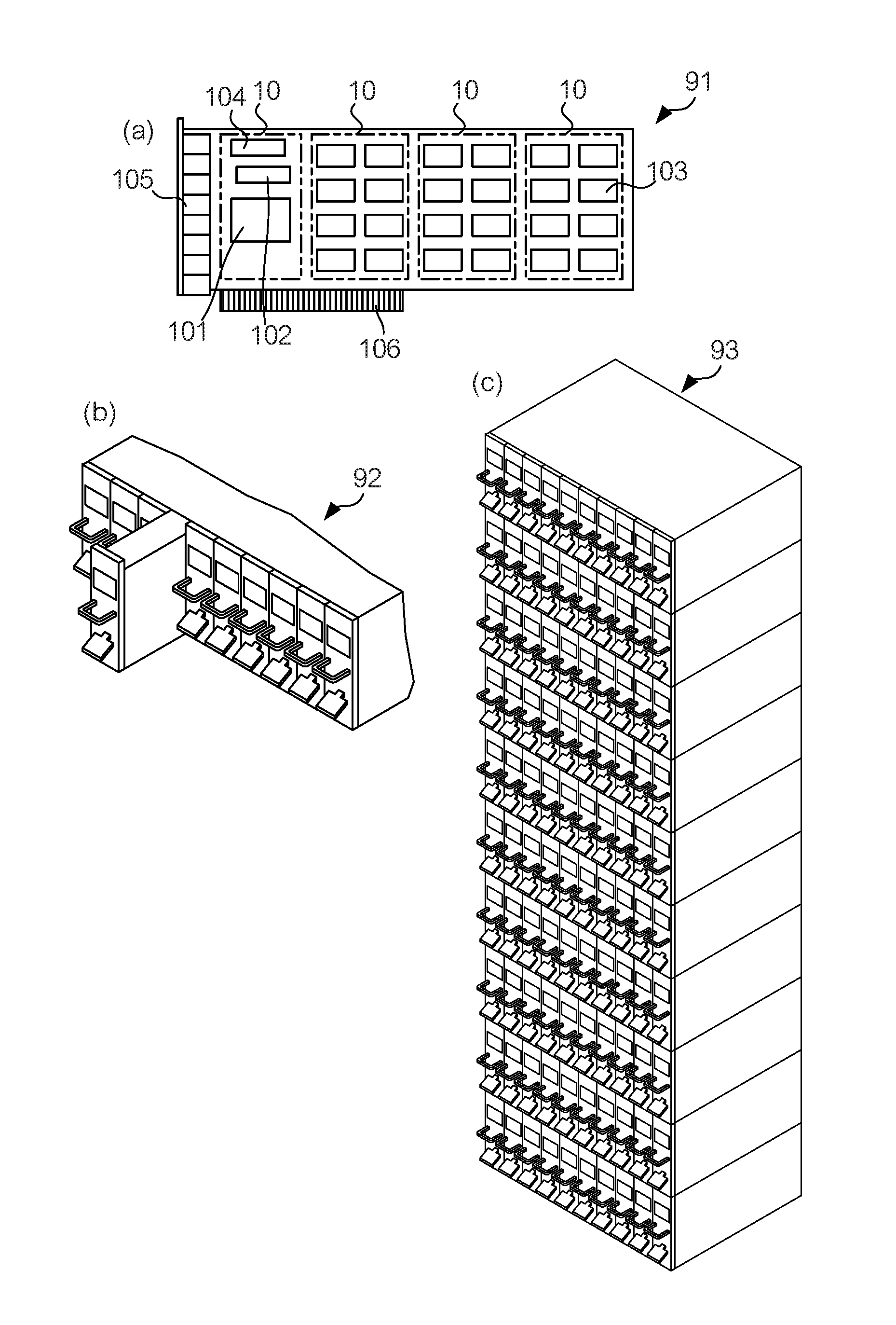
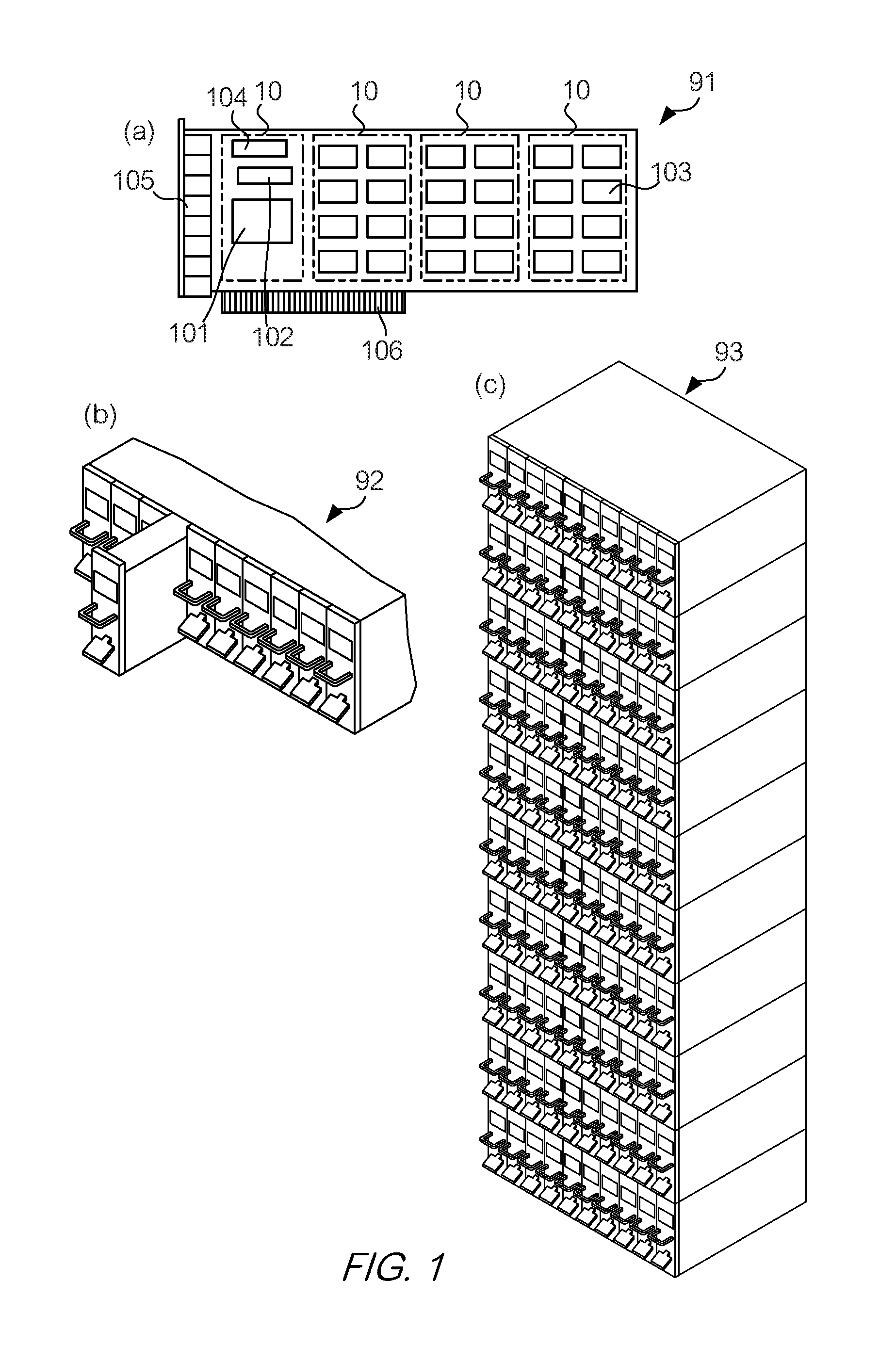
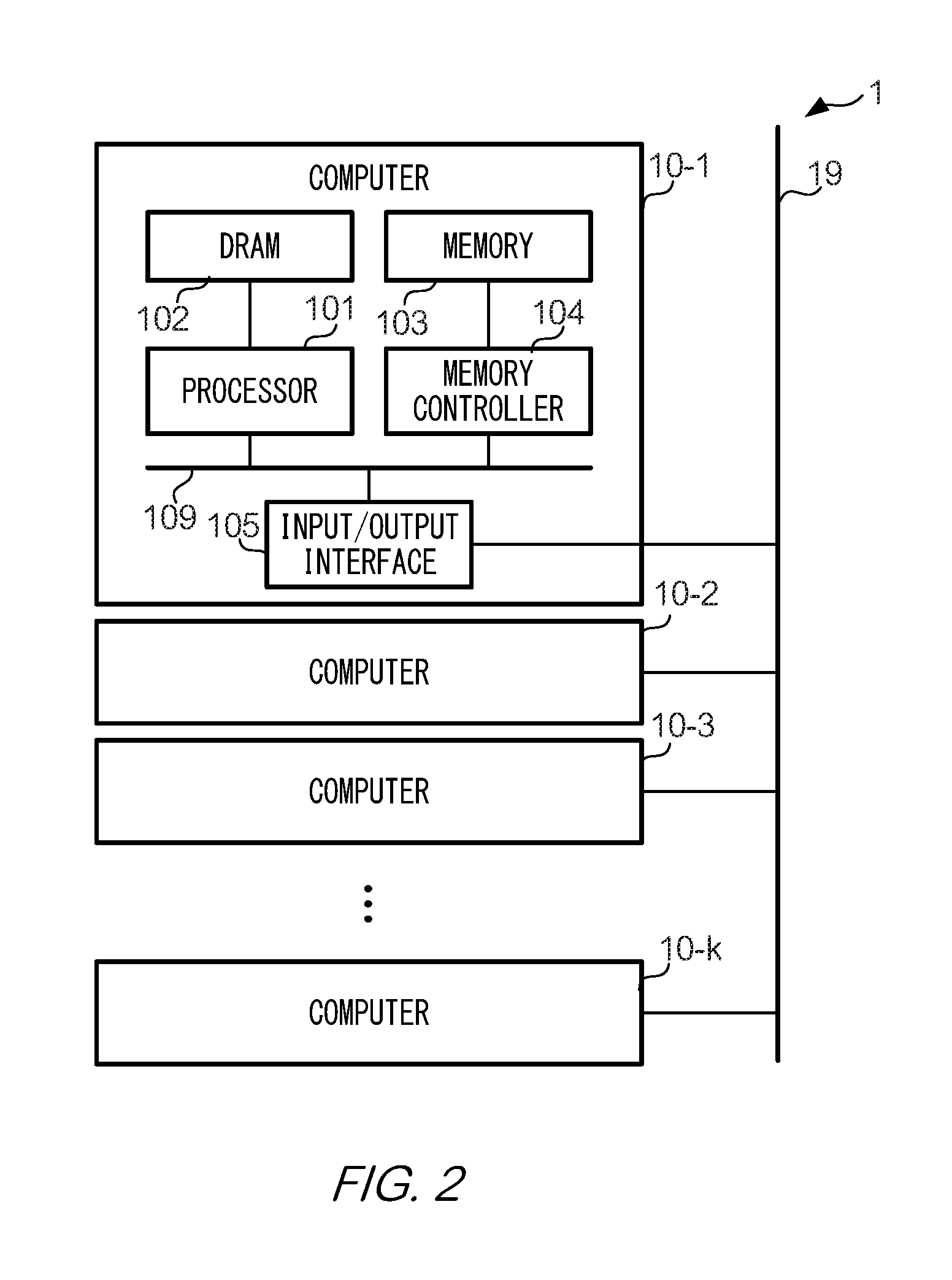
[0044]A data-processing system 1 as in one embodiment of the present invention is explained below. FIG. 1 is an external view of hardware of data-processing system 1. FIG. 2 is a block diagram illustrating a hardware configuration of data-processing system 1.

[0045]FIG. 1(a) shows the exterior of a card 91, in which four computers 10 are positioned. In FIG. 1(a), computer 10 positioned furthest to the left is shown with the memory module, normally positioned on the surface, removed. Each computer 10 comprises a processor 101 such as a CPU, which performs ordinary arithmetic operations, a DRAM 102 that is used by processor 101 as a main storage device, a memory 103 that is used by processor 101 as an auxiliary storage device, a memory controller 104 that is a processor that controls memory 103, and an input / output interface 105 that acquires data from and outputs data to other devices. In the present embodiment, input / output interface 105 is a communication interface that transmits an...

second embodiment

[0069]A data-processing system 2 as in a modified example of the present invention is explained below. The configuration of data-processing system 2 is the same in many regards as the configuration of data-processing system 1 as in the first embodiment. The explanation below will focus on the parts of the configuration of data-processing system 2 that differ from the configuration of data-processing system 1, and explanation of the parts of the configuration that are shared with the configuration of data-processing system 1 will be omitted as necessary. Those components of data-processing system 2 that are the same as or that correspond to the components of data-processing system 1 are assigned the same reference symbols as those used in the explanation of data-processing system 1.

[0070]FIG. 6 is a drawing illustrating the hardware configuration of data-processing system 2. Data processing system 2 comprises a computer 10 and h (where h is a natural number of 2 or more) data storage...

third embodiment

[0076]A data-processing system 3 as in a modified example of the present invention is explained below. The configuration of data-processing system 3 is the same in many regards as the configuration of data-processing system 1 of the first embodiment. The explanation below will focus on the parts of the configuration of data-processing system 3 that differ from the configuration of data-processing system 1, and explanation of the parts of the configuration that are shared with the configuration of data-processing system 1 will be omitted as necessary. Those components of data-processing system 3 that are the same as or correspond to the components of data-processing system 1 are assigned the same reference symbols as those used in the explanation of data-processing system 1.

[0077]FIG. 8 is a drawing illustrating the hardware configuration of data-processing system 3. Data processing system 3 comprises computer 10 and data storage device 30.

[0078]The configuration of computer 10 provi...


PUM


Abstract

The problem addressed by the present invention is to provide a means for suppressing a drop in overall performance that occurs when data rewriting is concentrated in a specific memory in a data-processing system comprising a plurality of memories, in which a number of possible rewrites is limited. A data-processing system as in one embodiment of the present invention comprises a management device and a plurality of data-processing devices. Each data-processing device comprises a memory, which is a NAND flash memory. Each data-processing device transmits, to management device, status data indicating a number of data rewrites to memory of the host device. Management device allocates data processing to the data-processing device having the smallest number of data rewrites indicated by the received status data.

Description

TECHNICAL FIELD[0001]The present invention pertains to a feature for extending a service life of a memory in which a number of times data can be rewritten is limited.BACKGROUND ART[0002]A number of times that data can be rewritten to a memory is subject to limitations. For example, a number of times that each storage element can be rewritten to a 2-bit MLC (Multiple Level Cell) NAND flash memory, the use of which has become widespread, is in the order of tens of thousands in practice. The limitation in the number of times that data can be rewritten to a flash memory is due to a gradual deterioration of a tunnel oxide film in a flash memory under passage of electrons upon each write operation.[0003]As noted, flash memory is subject to rewrite limitations. This is also the case for other types of memory such as compact disc-rewritable, CDRW, and Digital Versatile Disc rewritable DVDRW.[0004]Since limitations exist on a number of times that data can be written to a memory, if writing a...

Claims


Application Information

Patent Timeline
IPC IPC(8): G06F3/06
CPCG06F3/0616G06F3/0649G06F3/0653G06F3/0688G06F3/0689G06F11/3034G06F11/3055G11C16/349G06F3/0635G06F3/0659
Inventor YONEYA, SATOSHICHIKAMURA, KEISHI
Owner FIXSTARS SOLUTIONS
Why Eureka
Eureka Blog
Learn More