Method and system for monitoring smart structures utilizing distributed optical sensors

a distributed optical sensor and smart structure technology, applied in the measurement field, can solve the problems of many prior art sensors being electromechanical and cannot be placed into environments, many prior art sensors are too expensive, too dangerous, etc., and achieve the effects of not being able to meet the needs of us

Inactive Publication Date: 2005-07-05
ZIEBEL AS
View PDF13 Cites 439 Cited by
  • Summary
  • Abstract
  • Description
  • Claims
  • Application Information

AI Technical Summary

Problems solved by technology

Numerous fields require precise measurements of pressure, temperature, and/or strain but prior art methods are either too expensive, too dangerous, and/or too unsuited for use, e.g. due to inference caused or generated by the method.
By way of example and not limitation, many prior art sensors are electromechanical and cannot be placed into environments where gasses are volatile or into environments where either other machinery's electromagnetic interference (“EMI”) will affect the sensor or the sensor's EMI will affect the other machines.
This concern is due in part to the enormous expenses and risks associated with the execution of those processes, as well as environmental and safety factors.
However, these hydrates are not very stable and their dissociation can be slow or explosive depending on the chemical content and concentrations of the hydrates as well as changes in temperature and pressure.
For example, large vessels such as ocean ships often present hostile environments for electrical sensors, but these large vessels need sensors to provide ongoing, real-time data on stresses present in the vessel structure, e.g. pressure, strain, and the like.
The production of hydrocarbons may also cause the formations to compact, placing a burden on the casing and cement and sometimes causing the casing to fail which creates a potential hazardous condition and causes production to

Method used


Image

  • Method and system for monitoring smart structures utilizing distributed optical sensors
  • Method and system for monitoring smart structures utilizing distributed optical sensors
  • Method and system for monitoring smart structures utilizing distributed optical sensors

Examples


Embodiment Construction

[0045]In general, throughout this description, if an item is described as implemented in software, it can equally well be implemented as hardware.

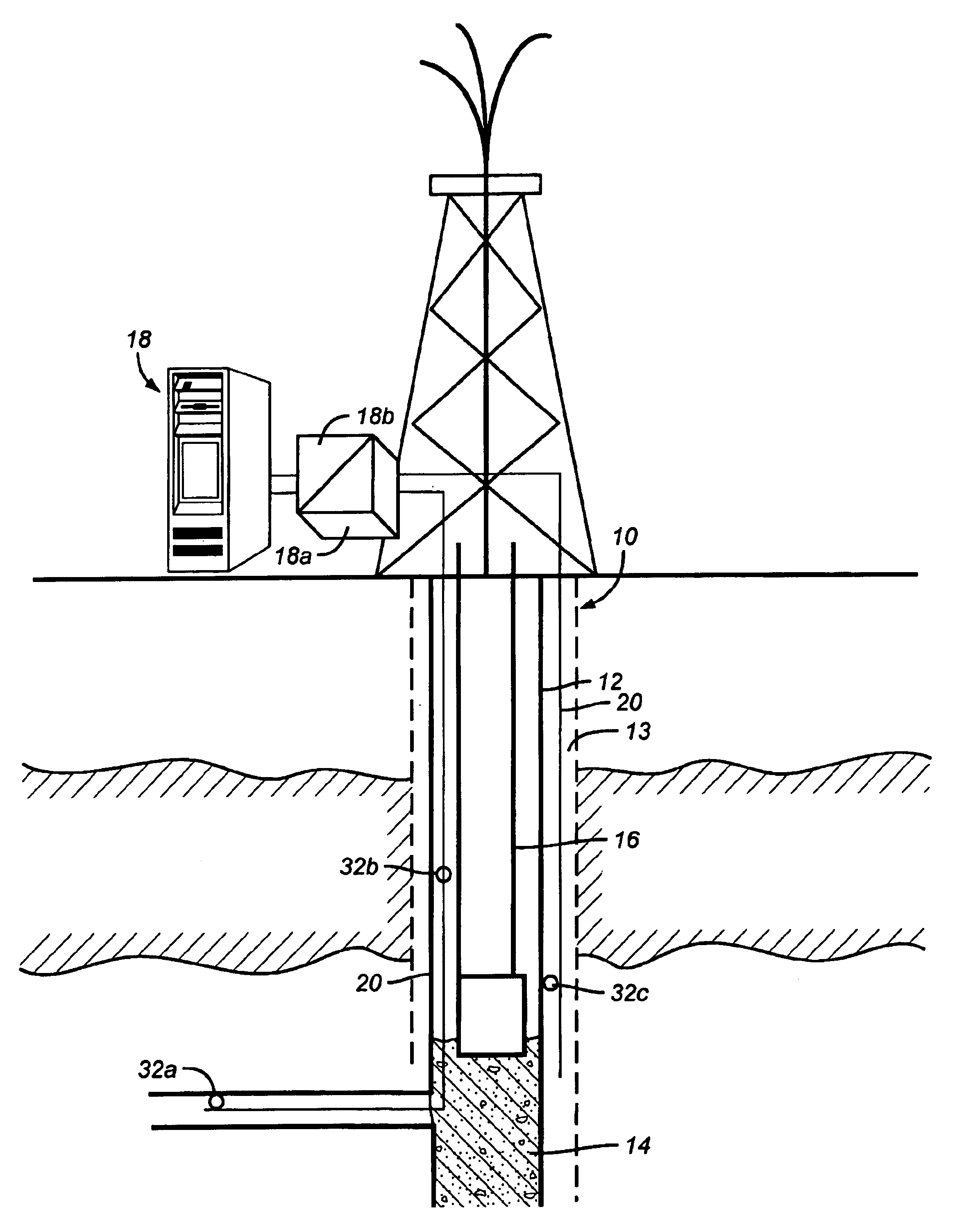
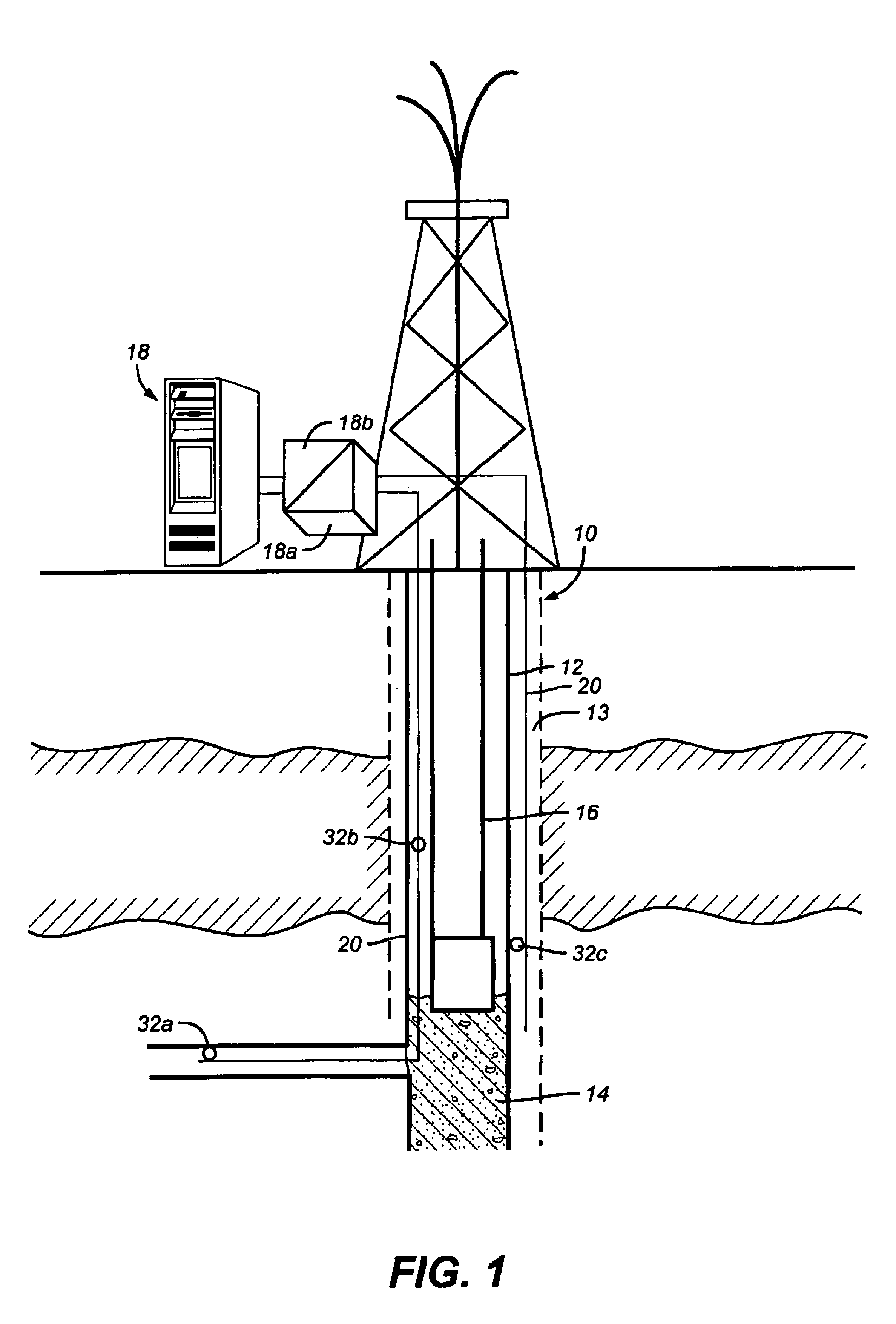
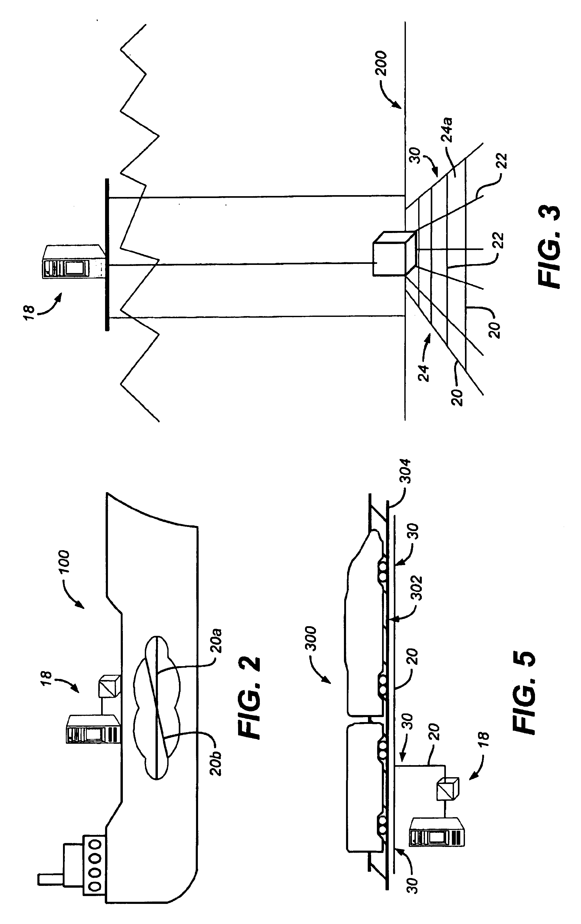
[0046]Although the oil and gas industry is used for exemplary reasons herein, the present invention's features and improvements apply to many fields including, by way of example and not limitation, monitoring stress and strain in structures such as nautical vessels 100 (shown in an exemplary representation in FIG. 2), roadways or railroad systems (shown in an exemplary representation in FIG. 5); monitoring stress and strain of structures located undersea, including evaluating methane hydrate stability undersea (shown in an exemplary schematic in FIG. 3 and FIG. 4); monitoring and testing drill stems; external monitoring and testing of wellbore tools such as casing packers, e.g. to insure that the cement was cured properly and the packer is sealing; monitoring reservoirs using pressure, temperature, and flow meters including build up and dr...


PUM


Abstract

A monitoring system and method for monitoring a predetermined set of physical characteristics associated with a structure using the monitoring system. The system is distributed in the structure and comprises a distributed optical sensing device (30), further comprising a fiber optic cable (20, 22); a light source (18a) operatively in communication with the fiber optic cable (20, 22); a light detection device (18b), operatively in communication with the fiber optic cable (20, 22), for measuring the light received at the light detection device (18b) from the fiber optic cable (20, 22); and a data processor (18) capable of using the light measured to calculate a predetermined set of physical parameters describing the predetermined set of physical characteristics.

Description

RELATED APPLICATIONS[0001]The present invention claims priority from U.S. Provisional Application No. 60 / 214,900 filed Jun. 29, 2000.BACKGROUND OF THE INVENTION[0002]1. Field of the Invention[0003]The present invention relates to the field of measurement. More specifically, the present invention, in an exemplary embodiment, relates to measurement of selected physical parameters for a predetermined environment using distributed optical sensors. More specifically still, the present invention, in an exemplary embodiment, relates to measurement of temperature, mechanical stress, pressure, vibration and mechanical strain using distributed fiber optic sensors in environments that require distributed measurements over long distances or continuous measurements where individual sensors would be prohibitive due to space constraints and / or costs.[0004]2. Description of the Related Art[0005]Numerous fields require precise measurements of pressure, temperature, and / or strain but prior art method...

Claims


Application Information

Patent Timeline
IPC IPC(8): E21B47/12E21B47/00E21B47/10G01N21/77
CPCE21B47/00E21B47/10E21B47/123E21B2043/0115G01N21/774G01V2210/647E21B41/0099E21B47/135G01V8/16E21B47/114
Inventor TUBEL, PAULO S.
Owner ZIEBEL AS
Why Eureka
Try Eureka