
Hardware-adaptable watermark systems

a watermark system and adaptable technology, applied in the field of hardware adaptable watermark systems, can solve the problems of uncertainty regarding the intensity and spectrum of lighting that illuminates the package, the scale, rotation or position of watermark blocks in captured imagery, and the increase of the variability of the focal distan

Active Publication Date: 2017-01-05
DIGIMARC CORP
View PDF6 Cites 45 Cited by
  • Summary
  • Abstract
  • Description
  • Claims
  • Application Information

AI Technical Summary

Benefits of technology

The patent text describes improvements to digital watermark systems, which are used to extract watermark data from imagery. The technical effects of the patent include improved synchronization and decoding stages that can better identify and decode the watermark data within the imagery. The synchronization stage uses reference signals to determine the transformation parameters of the watermark data, while the decoding stage uses error correction coding and other techniques to accurately extract the watermark data from the imagery. These improvements allow for more efficient and accurate watermark detection and extraction in various applications.

Problems solved by technology

When an image of such a watermarked object is captured by a camera, however, nothing is known about the scale, rotation, or position of the watermark blocks within the captured imagery.
But this latter application may have different challenges, such as uncertainty regarding the intensity and spectrum of the lighting that illuminates the package, and / or a greater variability in the focal distance.
However, hardware implementations have their own drawbacks, including substantial design and development costs.
Since each application has its own design constraints and parameters, it has generally not been cost-effective to develop a hardware design for each, because such parts would typically not be manufactured in sufficient volume to bring per-unit costs down to an acceptable level.

Method used

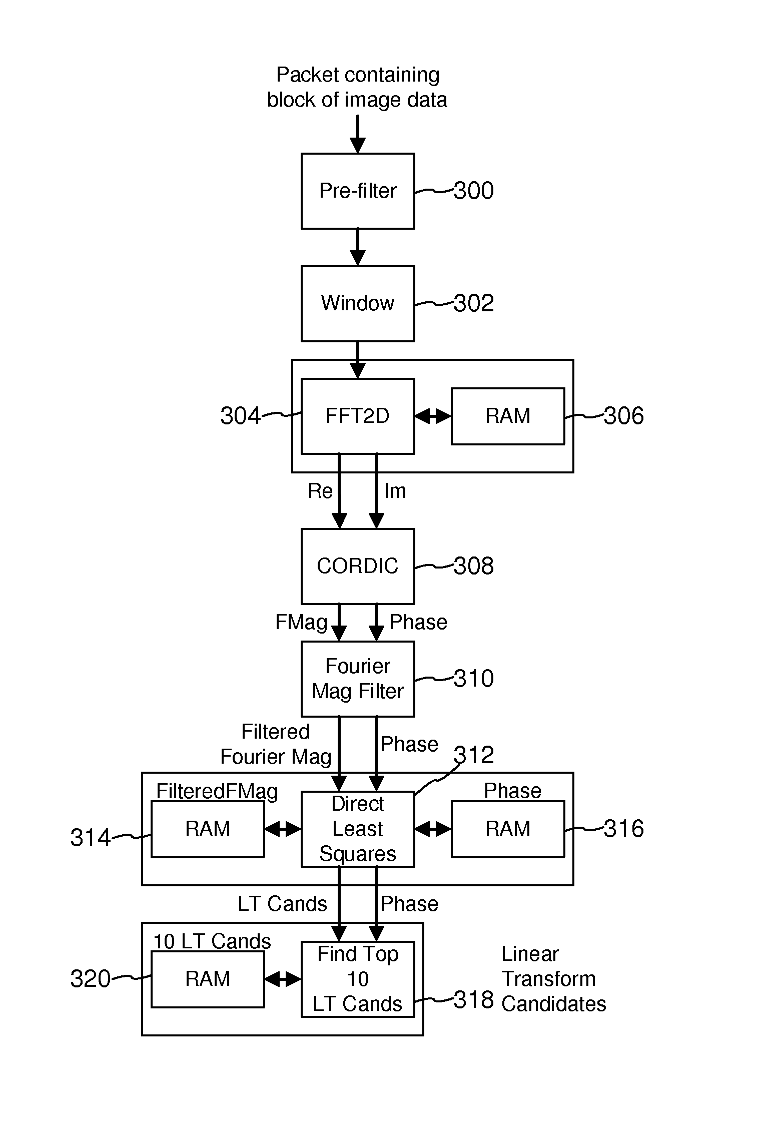
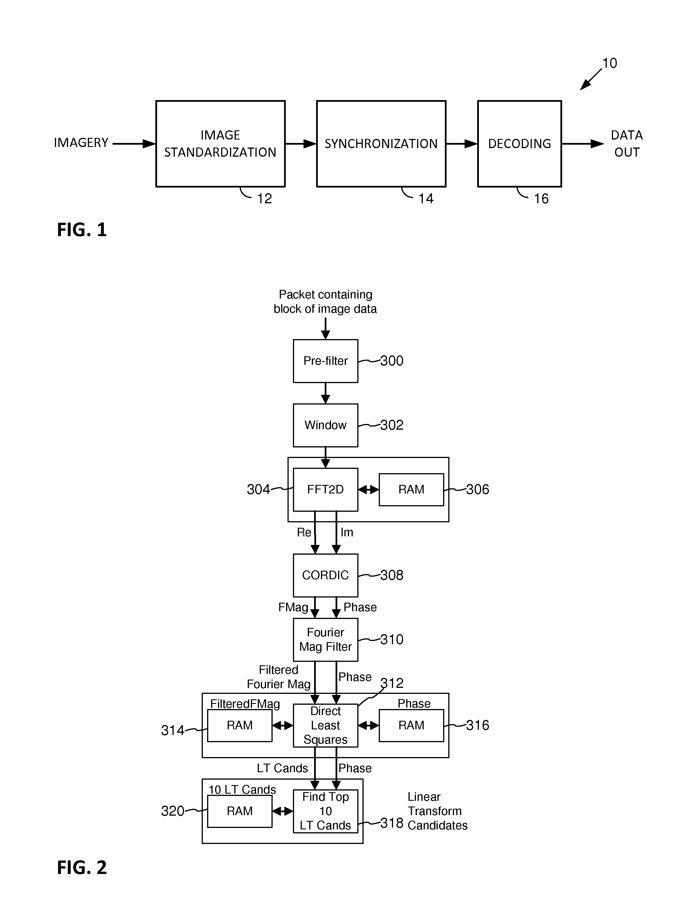
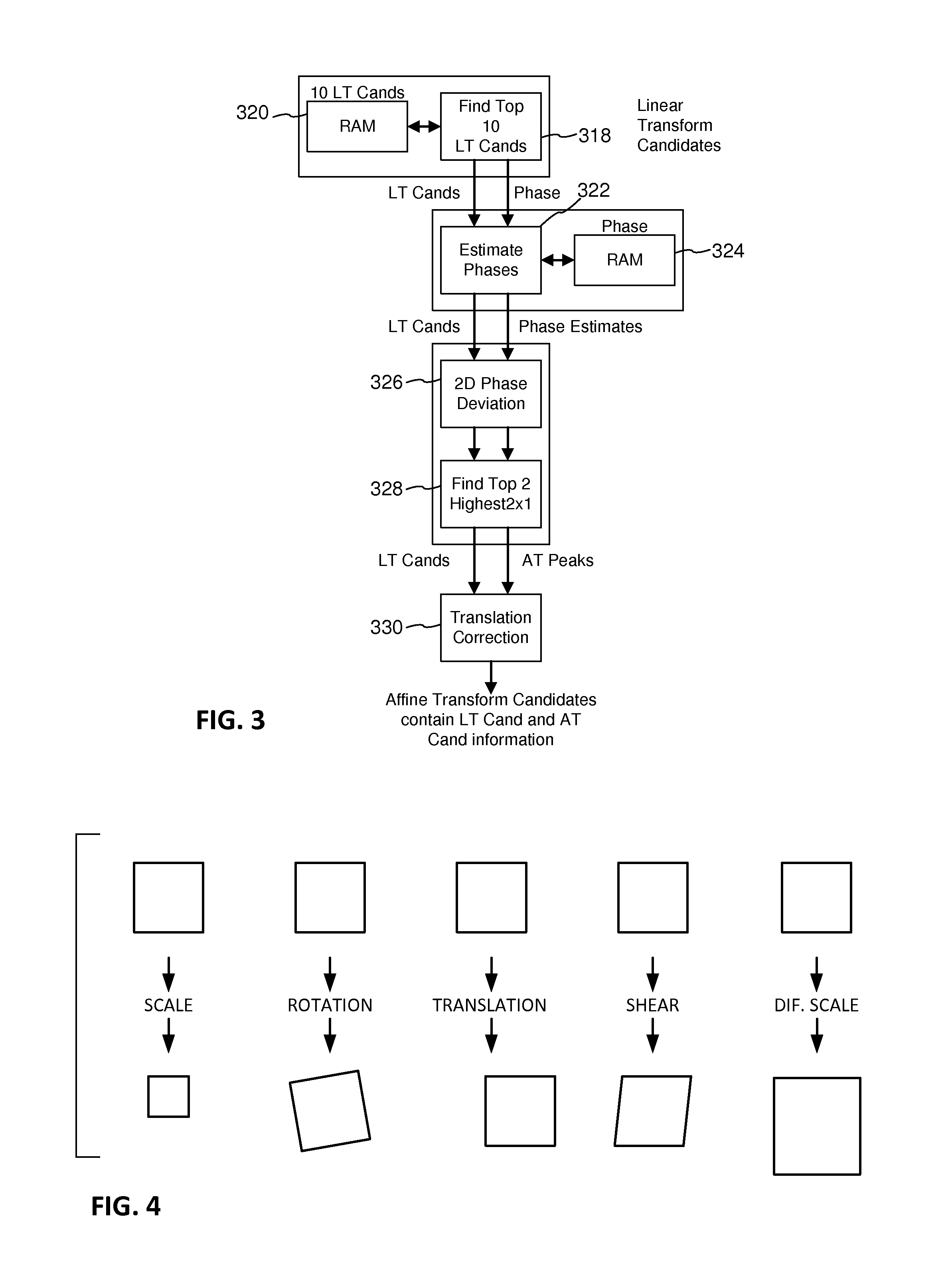

Image

  • Hardware-adaptable watermark systems
  • Hardware-adaptable watermark systems
  • Hardware-adaptable watermark systems

Examples


Embodiment Construction

[0028]Applicant details, below, several different forms by which watermark systems can be made reconfigurable in hardware.

[0029]FIG. 5 shows a first such hardware system 50. This arrangement includes the image standardization, synchronization, and decoding stages of FIG. 1, but depicted in greater detail. Each such stage is implemented as a pipelined series of modules, each of which performs a different part of the overall process.

[0030]Some or all of these modules are implemented in ASIC form, e.g., using known techniques as detailed below. But, importantly, at least one or more of the modules includes one or more registers into which parameter(s) that tailor some aspect of the module's operation are stored. If the hardware system 50 is employed in a retail, fixed POS scanner, one set of parameters can be employed. If employed in a handheld scanner, another set of parameters can be employed. If employed in a consumer smartphone, still another set of parameters can be employed. If e...


PUM


Abstract

There are many advantages to implementing a watermark-based system using dedicated hardware, rather than using software executing on a general purpose processor. These include higher speed and lower power consumption. However, hardware implementations incur substantial design and development costs. Moreover, because each watermarking application has its own design constraints and parameters, it has not been cost-effective to develop a hardware chip design for each, since such chips would typically not be manufactured in volumes sufficient to bring per-unit costs down to an acceptable level. The present technology provides various techniques for making watermarking hardware adaptable, so that a single chip can serve multiple diverse watermark applications. By so-doing, the advantages of hardware implementation are made available where it was formerly cost-prohibitive, thereby enhancing operation of a great variety of watermark-based systems.

Description

RELATED APPLICATION DATA[0001]This application claims priority to pending provisional applications 62 / 188,440, filed Jul. 2, 2015, and 62 / 196,876, filed Jul. 24, 2015, the disclosures of which are incorporated herein by reference, in their entireties.TECHNICAL FIELD[0002]The present technology concerns improvements to the design and operation of digital watermark systems.INTRODUCTION[0003]Digital watermark systems are detailed in a variety of applicant's previously-published documents, including U.S. Pat. Nos. 6,590,996 and 8,886,206, and application 20120078989, the disclosures of which are incorporated herein by reference.[0004]For clarity of description, the present discussion focuses on arrangements that decode watermark-encoded data from imagery. However, the same principles are likewise applicable to systems that perform the complimentary predecessor operation, namely encoding watermark data into imagery.[0005]FIG. 1 shows basic elements of an exemplary watermark decoding syst...

Claims


Application Information

Patent Timeline
IPC IPC(8): G06T1/00H04N19/42H04N19/44
CPCG06T1/0064G06T2201/0065G06T2200/28H04N19/467G06T2200/08H04N19/42G06T1/005
Inventor BOLES, JACOB L.SHARMA, RAVI K.LORD, JOHN D.
Owner DIGIMARC CORP
Learn More